Buzby
Senior Member
Hi All,
The next challenge I have is to turn my PICaxe 'on' with a push-button, then 'off' under software control. ( This part of the project is a handheld device with a few buttons and LEDS. It's just the sort of thing that someone will forget to turn off when they've finished using it !.)
I found this gadget, http://www.pololu.com/catalog/product/750 but it seems a bit of overkill, especially if my attached circuit has a chance of working.
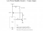
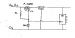
The logic is quite simple. Pressing the PB turns on the FET, thus powering the PICaxe. The PICaxe then drives the output low, thus keeping the FET conducting. When the time is right the PICaxe drives the output high, which turns off the FET.
Has anybody tried anything like this ?. Are there any pitfalls I might run into ?.
The next challenge I have is to turn my PICaxe 'on' with a push-button, then 'off' under software control. ( This part of the project is a handheld device with a few buttons and LEDS. It's just the sort of thing that someone will forget to turn off when they've finished using it !.)
I found this gadget, http://www.pololu.com/catalog/product/750 but it seems a bit of overkill, especially if my attached circuit has a chance of working.
The logic is quite simple. Pressing the PB turns on the FET, thus powering the PICaxe. The PICaxe then drives the output low, thus keeping the FET conducting. When the time is right the PICaxe drives the output high, which turns off the FET.
Has anybody tried anything like this ?. Are there any pitfalls I might run into ?.
Attachments
-
 20.9 KB Views: 77