westaust55
Moderator
Initially some theory that may be of interest to others, and then a question at the end for our more radio orientated members.
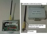
Having late last year purchased some 433.92MHz Keymark Tx and RX modules from Jaycar, I did some research and Googling to find out a bit more about any limitations of use.
While there are a number of threads on this forum, most discuss the maximum range for their modules and maybe the length of a simple piece of wire as an antenna.
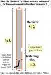
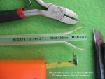
I did find an Instructables article by Dr Acula who set up a dipole antenna for greater distance with a PICAXE project. Research suggested that a 1/2 wave dipole has a gain of 2.15 dBi (in free space – read as "well above the ground").
Manuka (Stan) also has an article in the Silicon Chip Magazine for Jan 2006 on this topic. In this article Stan mentions:
“Radiocommunications (Low Interference Potential Devices) Class Licence Variation Notice 2008 (No. 1)”.
Under item 17, for the 434MHz band, the same 25mW EIRP still applies.
Started thinking about possible extension of the dipole antenna to a small Yagi antenna with say 3 elements (add a reflector and director) to be able to cover some distance and penetrate several brick walls.
The mandatory EIRP is calculated using this formula:
EIRP = Pout + Gt – Ct
Where:
The Jaycar sold 433MHZ transmitter module has a rated Output power of 3 dBm with Vcc = 3 V into a 50 Ohm load.
Lets say I have a few metres of Low loss RG-213, 50 Ohm coaxial cable (available from Dick Smith). Attenuation will be around 0.5 dB for 3 metres.
Conversion from mW to dBm gives: 25 mW = 13.97940008672 dBm
Therefore, from EIRP = Pout + Gt – Ct
we get Gt = EIRP – Pout + Ct
so, Gt = 13.9 – 3 + 0.5 = 11.5 dBi
Reference to some Amateur (ARRL) type/member sites suggest the a 3 element yagi antenna has a theoretical gain of around 8 to 9 dBi in free space, but other sources/calc suggest typical as ~ 7 dBi and as low as ~5 dBi.
So in theory, a small(ish) 3 element Yagi antenna could be used and still remain within the relevant regulations. By smallish the overall width would be around ~360mm (reflector) and the beam length around ~140mm which is still very portable (to me at least).
For those who are interested, here are some Australian Govt based links on the topic.
http://www.acma.gov.au/WEB/STANDARD/pc=PC_2643
http://www.acma.gov.au/WEB/STANDARD/1001/pc=PC_2633
http://users.bigpond.net.au/vk3yng/lipd/aca_resp01.htm
Note that Australia is part of ITU Region 3.
The band 433.05 to 434.79 MHz is not a designated ISM band in Australia.
Noting that some others have amateur radio experience, here is the question:
Can anyone see any flaws in my thoughts/calcs before I dash out and buy some hardware to make a “better” antenna ?
EDIT:
some further information for those in Australia (from Australian Communications Authority correspondence):
The band 433.05 MHz to 434.79 MHz is shared by amateur radio, low-powered applications and the
radiolocation service. The radiolocation service is the only primary service in this band. Other services
operating in this band must not cause harmful interference to the primary service, and are not afforded
protection should they receive harmful interference from that primary service.
also for reference:
ISM Band = The Industrial, Scientific and Medical (ISM) radio bands were originally reserved internationally for non-commercial use of RF electromagnetic fields for industrial, scientific and medical purposes.
Having late last year purchased some 433.92MHz Keymark Tx and RX modules from Jaycar, I did some research and Googling to find out a bit more about any limitations of use.
While there are a number of threads on this forum, most discuss the maximum range for their modules and maybe the length of a simple piece of wire as an antenna.
I did find an Instructables article by Dr Acula who set up a dipole antenna for greater distance with a PICAXE project. Research suggested that a 1/2 wave dipole has a gain of 2.15 dBi (in free space – read as "well above the ground").
Manuka (Stan) also has an article in the Silicon Chip Magazine for Jan 2006 on this topic. In this article Stan mentions:
In January 2009, The Australian Govt issued a new variation to the Class License as:YES! – it’s legal, as the only Australian/NZ 433.92MHz LIPD ISM regulatory restriction is that the transmitter should not exceed 25mW EIRP (Effective Isotropic Radiated Power).
“Radiocommunications (Low Interference Potential Devices) Class Licence Variation Notice 2008 (No. 1)”.
Under item 17, for the 434MHz band, the same 25mW EIRP still applies.
Started thinking about possible extension of the dipole antenna to a small Yagi antenna with say 3 elements (add a reflector and director) to be able to cover some distance and penetrate several brick walls.
The mandatory EIRP is calculated using this formula:
EIRP = Pout + Gt – Ct
Where:
Pout = transmitter power output (dBm)
Ct = signal loss in cable (dB)
Gt = gain of the antenna (dBi)
Ct = signal loss in cable (dB)
Gt = gain of the antenna (dBi)
The Jaycar sold 433MHZ transmitter module has a rated Output power of 3 dBm with Vcc = 3 V into a 50 Ohm load.
Lets say I have a few metres of Low loss RG-213, 50 Ohm coaxial cable (available from Dick Smith). Attenuation will be around 0.5 dB for 3 metres.
Conversion from mW to dBm gives: 25 mW = 13.97940008672 dBm
Therefore, from EIRP = Pout + Gt – Ct
we get Gt = EIRP – Pout + Ct
so, Gt = 13.9 – 3 + 0.5 = 11.5 dBi
Reference to some Amateur (ARRL) type/member sites suggest the a 3 element yagi antenna has a theoretical gain of around 8 to 9 dBi in free space, but other sources/calc suggest typical as ~ 7 dBi and as low as ~5 dBi.
So in theory, a small(ish) 3 element Yagi antenna could be used and still remain within the relevant regulations. By smallish the overall width would be around ~360mm (reflector) and the beam length around ~140mm which is still very portable (to me at least).
For those who are interested, here are some Australian Govt based links on the topic.
http://www.acma.gov.au/WEB/STANDARD/pc=PC_2643
http://www.acma.gov.au/WEB/STANDARD/1001/pc=PC_2633
http://users.bigpond.net.au/vk3yng/lipd/aca_resp01.htm
Note that Australia is part of ITU Region 3.
The band 433.05 to 434.79 MHz is not a designated ISM band in Australia.
Noting that some others have amateur radio experience, here is the question:
Can anyone see any flaws in my thoughts/calcs before I dash out and buy some hardware to make a “better” antenna ?
EDIT:
some further information for those in Australia (from Australian Communications Authority correspondence):
The band 433.05 MHz to 434.79 MHz is shared by amateur radio, low-powered applications and the
radiolocation service. The radiolocation service is the only primary service in this band. Other services
operating in this band must not cause harmful interference to the primary service, and are not afforded
protection should they receive harmful interference from that primary service.
also for reference:
ISM Band = The Industrial, Scientific and Medical (ISM) radio bands were originally reserved internationally for non-commercial use of RF electromagnetic fields for industrial, scientific and medical purposes.
Last edited: