Decoding UK's NPL MSF Time Signal

My first real post, so be gentle with me!

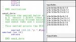
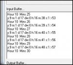
Attached is a programme that decodes the time signal provided by the UK's National Physics Lab.This in known as "MSF" and is broadcast from Anthorn, Cumbria,UK. It should be capable of being picked up in nothern and western Europe.

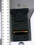
This project came about because my "radio controlled" radio alarm went defunct, but the antenna and its electronics were OK. The clock was similar to the one here http://www.leapsecond.com/pages/sony-wwvb/

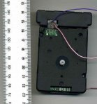
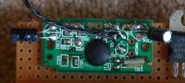
In fact the antenna module is pretty much identical, using the Temic U4226B chip.(The datasheet available on the web).

So I thought I'd have a go at decoding the signal, aiming at using the cheapest 'axe.

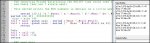
The resulting code is attached - which doubtless could be improved upon.
It is not a "full" decode of the signal, most importantly NOT parity checking the Time and Date data. (Not enough code-space in the 08M). This may seem "catastrophic" but it seems to work pretty well, despite this.

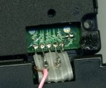
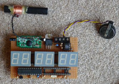
There is not much hardware involved outside the antenna module.
The output from the U4226B chip is inverted i.e. gives a logic high for carrier off. This I re-inverted using a BC548B transistor switch (100K base resistor, 2K7 load res.).

A setup such as this could be used to contain the "drift" over time of a DS1307 RTC (or similar) - well thats why my radio alarm clock had one!

Hope this code may be useful to someone.
 

Attachments

eclectic,
Hmm! How's your antenna? (excuse this intimate question). I get hours running without a glich. My antenna is 3 ft away from my laptop with the ferrite rod at right angles to broadast signal.
 

eclectic

Moderator
eclectic,
Hmm! How's your antenna? (excuse this intimate question). I get hours running without a glich. My antenna is 3 ft away from my laptop with the ferrite rod at right angles to broadast signal.
OO-err.

The clock module is ~2 feet from the computer and monitor,
resting on a 2 ft box.

e
 
eclectic,
sorry about my last post - a "somewhat" obtuse way of saying you need a very clean signal for consistantly good functioning - itself a blndingly obvious statement.

What is the antenna hardware you are hacking?
 
Last edited:

MartinM57

Moderator
eclectic,
...you need a very clean signal for consistantly good functioning - itself a blndingly obvious statement.
That's what I found when I did this also - as I want to operate in a mobile environment I found that parity checking was essential or else you can decode the signal from the individual bits to a valid but completely erroneous time.

When stationary with a good signal it was fine, otherwise it was a bit hit and miss.

Fancy trying to do a minimalist code parity checker for us all.. :D
 
Martin

I found that parity checking was essential or else you can decode the signal from the individual bits to a valid but completely erroneous time.
Question: Is parity checking "fool proof"?

There is always the possibility of "two wrongs making a right" in parity checking - I'm not sure what probability might be - it will be low(?). So parity checking is not fool proof per se.

Question: Is it better (than parity checking) to compare a set of Time and Data values, say a minute apart and if consistent deem the time correct?
Also to check this time with the RTC and if not within some tolerance, then reject the update.

I don't know the answer to this question - a mathematician needed here!

Fancy trying to do a minimalist code parity checker for us all..
It would be easy to extend the code to cover parity checking, but you will not get the code into an 08M...don't let me stop you!!

Cheers

Richard
 
Last edited:

hippy

Technical Support
Staff member
I've wanted to get into MSF decoding so may have been inspired to do so. Key to usefulness to others IMO is having cheap(ish) hardware people can easily buy off the shelf and circuits to use it with a PICAXE. The Temic and similar modules are probably best and easiest to use but finding product that uses them, and at a reasonable price, may not always easy.

@ eclectic : Can you give us more info on the Argos clock ? Is the MSF decoder a separate PCB, easy to use, supply voltage, and what's needed to interface to a PICAXE ?

On the subject of decoding, there are really two approaches to add parity checking and data verification and validation; a bigger PICAXE or multiple cheap PICAXE's. If prepared to pay a reasonable amount for the MSF receiver it is perhaps false economy to skimp on the extra PICAXE cost if one wants a more robust decoder. Ideally multiple approaches should be used, parity checking per packet, checking the packet is a valid date and time, verifying consecutive packets make chronological sense.

What the best choice is depends greatly on what one wants to achieve. I'd personally like something which puts out the time serially every second, filling in the gaps when the MSF signal is off-air or too unreliable for use. That could get quite complicated. Very complicated if you also wanted a marker character to appear exactly on a seconds change. I expect most people would be happy with something which is accurate to the second and handles DST automatically.
 

eclectic

Moderator
@Hippy.

Pic 1 shows the back of a working clock. 1 x AA.
Pic 2 is from a hacked/mangled clock, from the face side.
Pic 3 (next post), are the connectors.

Five connections, labelled
VDD / RF / VSS / PON / AGC

PON is grounded to the battery negative.
'Scope signals show on RF-VDD or an inverted signal RF-PON/gnd
I'm presently using RF/VDD, then an LM324 which inverts.

It's been working for the seconds counter
http://www.picaxeforum.co.uk/showthread.php?t=11306

It also works with Greypower's code above.

I think I'll buy a couple more to play with and try and do it properly. :)
 

Attachments

MartinM57

Moderator
I hacked (aka removed the receiver from) an Oregon Scientific clock. I eventually traced the part number on the receiver PC to a trade supplier in the UK.

He wanted something like £14 ea. for min order of 500 - I paid £9.99 for the clock ;)
 
Last edited:

hippy

Technical Support
Staff member
There seem to be many digital clocks under £10

Indeed, but are they usable or is it simply spending money on something which cannot be used easily with a PICAXE ?

I've got quite a few MSF clocks but haven't been able to determine how they could be used ( single Chip On Board black blobs ) and even if I could work that out and detail how to use such a clock for others then I doubt anyone else would have the same clock.

I think there would be more interest in MSF decoding if people could be told to "buy this, do that" and be more confident it would work. People are reluctant to try something they are unfamiliar with if they don't know what to use or how to use it.

This is why most solutions for project ideas involve directing people to commercial solutions which have ready-built product ( AXE033 for LCD control, SRF04 for ultrasonic sensors ) or to ubiquitous products which can be repurposed ( "pull one out of a Furby, see here for instructions" ). Less than that and it becomes less achievable or realistic for most people.

The problem for most who may be interested in MSF decoding is that commercial modules are very expensive and there hasn't been that ubiquitous product those interested can be pointed towards.
 

BeanieBots

Moderator
I agree that the core problem is "which module".
However, the coded transmission will always be the same no matter what.
The UK signal is broadcast from Rugby on 60kHz VLW.

I wouldn't have thought it was too tricky to build a radio+detector at such a low frequency. Ferrite with X turns, diode+cap + simple amplifier, probably just a single tranny. Just a question of somebody with a little radio knowledge to supply the values.

Then it would just down to a PICAXE to decode the data-stream possibly with pulsin. No idea how quick the bits arrive so might be impossible without a fast PIC. Anyone got any figures for it?
 

eclectic

Moderator
@greypower.

You've done a massive amount of work on this project.
All credit to you.
All I'm doing is adding a little bit, to help my poor addled brain cell.

I'm using a 28X1, so, plenty of variables and code-space.
I added three more symbols, using b14-b16.
Then I added the routines I've shown in the screen-shot,
to convert the #BCD to decimal.

e.
 

Attachments

hippy

Technical Support
Staff member
Well I'm a proud owner of an Argos clock (255/1966). Quite magical watching an analogue clock set it itself to correct time. Unlike eclectic though I don't think mine's ever going to work as an analogue clock again. Do not pull the centre section apart or half the gears fall out :)

The clock mechanism is in three parts, once detached from the clock body the end bits slide off ( only remove the centre screw for the T-shaped MSF module ). The section near the battery only contains two switches on a PCB. The main section holds the battery, micro (COB), two 'solenoids' and the gearing. The T-shaped section holds the MSF receiver plus aerial. Haven't pulled that fully apart because I didn't want to damage the aerial leads.

All the PCB interconnects are a bit fragile and can snap open-circuit. I've removed the MSF section entirely and have flying wires to the main section, solely for AGC. Now to connect a scope and see what signals there are.
 

BCJKiwi

Senior Member
Re the parity checking;

In this instance, perhaps this could be replaced by sanity checking.

Since time is advancing then any result that is earlier than the last can be discarded. Similarly any result that is too far ahead can be discarded.

Naturally startup and leap year issues would need to be handled as well.
 

hippy

Technical Support
Staff member
That clock was money well spent ( measured against the equivalent beer at the same cost and how long it keeps me amused ).

I cannot get greypower's code to work but have got an 08M beeping every minute and 60 pulses detected every minute.

I'm feeding the "RF" (demodulated) signal straight into an 08M TTL-level input pin, power supply at 2V5 . No level shifting or inversion needed.

Code:
Symbol SIGNAL  = pin4       ' Signal Input Pin
Symbol PIEZO   = 1          ' Piezo Output Pin

Symbol ACTIVE  = 1          ' Active level ( 0 or 1 )

Symbol bitTime = b0

Symbol INACTIVE = ACTIVE ^ 1

Do
  Gosub ReadBit
  if bitTime = 5 then
    sound PIEZO,(100,20)
  end if
  SerTxd(#bitTime)
Loop

ReadBit:
  bitTime = 0
  Do : Loop Until SIGNAL IS INACTIVE
  Do : Loop Until SIGNAL IS ACTIVE
  Pause  50
  If SIGNAL IS ACTIVE Then
    Do
      bitTime = bitTime+1 
      Pause 100      
    Loop Until SIGNAL IS INACTIVE Or bitTime = 0
  End If
  Return
 

hippy

Technical Support
Staff member
It seems to be working, showing what was last received every minute, but an attempt to fill in the seconds and track real time wasn't so successful.

This is far more tricky than first appears. When the 500ms 'pulse' occurs it indicates the start of a minute, but you don't know what that minute is until 52 seconds later. If you simply dump the packet received so far with a seconds value tagged on it changes at 52 seconds. Similar effects on any rollover, and for a year change, consecutive seconds will show the year, month, day etc changes rippling through a bit at a time, very confusing. But, if you use the previous packet you are always behind by one minute.

To send out an accurate "the time is now...", you need to read what the time was, calculate in software what the time will be ( taking into account roll-over of everything, minutes through year, including leap years ) and use that for output.
 
Hippy - do you ever sleep? It was 5a.m. for last post and I think fatigue must have been setting in!

From the NPL spec. of the time signal:

"The time and date code information is always given in terms of UK clock time and date, which is UTC in winter and UTC+1h when Summer Time is in effect, and it relates to the minute following that in which it is transmitted."

(Bold italics mine)

I wonder why my code will not work on an 08M? Any ideas, I don't have one currently so can't test.

Eclectic, what processor did you use for this code?

Cheers GP
 
Last edited:

hippy

Technical Support
Staff member
Hippy - do you ever sleep? It was 5a.m. for last post and I think fatigue must have been setting in!
First time in a while I've been up this late, so I think it's safe to say the challenge has captured my interest.

"The time and date code information is always given in terms of UK clock time and date, which is UTC in winter and UTC+1h when Summer Time is in effect, and it relates to the minute following that in which it is transmitted."
You're right, thanks for pointing that out, it must have been fatigue.

Using what was last received during the time the current is being received to show what the time is now, does have that bit ripple problem as described and I think the lateness of the hour confused me as to what was going on.


I wonder why my code will not work on an 08M? Any ideas, I don't have one currently so can't test.
It probably will work. I think it's more an issue of not working with different I/O pins and different polarities without code changes. There are a couple of places where changing the SYMBOL definitions do not change the code (SETINT, PULSIN ).

Now I know there's not a major chunk of work in predicting the time to come next, I'll update my code, get it working and then post that.
 
Re the parity checking;

In this instance, perhaps this could be replaced by sanity checking.

Since time is advancing then any result that is earlier than the last can be discarded. Similarly any result that is too far ahead can be discarded.

Naturally startup and leap year issues would need to be handled as well.
@BJC - thanks for what I take to be a "get real" call.

@eclectic - well done with the 08M! Speedy stuff.
 

MartinM57

Moderator
@BJC - thanks for what I take to be a "get real" call.
With respect - which means "I don't agree!", of course - I think the devil is in the detail and you'd spend a lot more time trying to define and code "too far ahead" etc

Plus the startup issue is non-trivial - imagine building a product that the first time it was switched on was when the user opened the box, was in a strong signal area and expected a 'fix' asap.

You miss the first minute as it's turned on 5 secs into the minute, the second says A, the third gives B, B-A is greater than one minute so you wait for the fourth minute etc

But if you parity checked the second minute, and it checked out OK, you could confidently go with it.

The code's not difficult - imagine a block of memory based at SecondBase where each entry is the data value for each second in the minute (bit 0 is the A bit, bit 1 is the B bit)...(no attempt at memory conservation or code efficiency - there's lots of room in a 28X)

Code:
'##############################################################
'Test that the MSF parity checks pass
'##############################################################
test_parity:

tp1:
	MSF_ERROR = 0
	b3 = 0
	'Count 17A - 24A...
	for b0 = 17 to 24
		b1 = SecondBase + b0
		peek b1, b2
		b3 = b2 // 2 + b3
	next
	'...add 54B...
	b1 = SecondBase + 54
	peek b1, b2
	b3 = b2 / 2 + b3
	b3 = b3 & %00000001
	'...should be odd...
	if b3 = 1 then tp2
	b3 = 1
	goto tp_fail

tp2:
	b3 = 0
	'Count 25A - 35A...
	for b0 = 25 to 35
		b1 = SecondBase + b0
		peek b1, b2
		b3 = b2 // 2 + b3
	next
	'...add 55B...
	b1 = SecondBase + 55
	peek b1, b2
	b3 = b2 / 2 + b3
	b3 = b3 & %00000001
	'...should be odd...
	if b3 = 1 then tp3
	b3 = 2
	goto tp_fail

tp3:
	b3 = 0
	'Count 36A - 38A...
	for b0 = 36 to 38
		b1 = SecondBase + b0
		peek b1, b2
		b3 = b2 // 2 + b3
	next
	'...add 56B...
	b1 = SecondBase + 56
	peek b1, b2
	b3 = b2 / 2 + b3
	b3 = b3 & %00000001
	'...should be odd...
	if b3 = 1 then tp4
	b3 = 3
	goto tp_fail

tp4:
	b3 = 0
	'Count 39A - 51A...
	for b0 = 39 to 51
		b1 = SecondBase + b0
		peek b1, b2
		b3 = b2 // 2 + b3
	next
	'...add 57B...
	b1 = SecondBase + 57
	peek b1, b2
	b3 = b2 / 2 + b3
	b3 = b3 & %00000001
	'...should be odd...
	if b3 = 1 then tp_end
	b3 = 4

tp_fail:
	MSF_ERROR = 1

tp_end:
	'debugging here if wanted
	'if MSF_ERROR = 0 then tp_return
	'sertxd ("Parity ", #b3, " fail", 13, 10)

tp_return:
	return
 
Last edited:

hippy

Technical Support
Staff member
Here's my version for an 08M. A distinct lack of comments I'm afraid. It takes at least two minutes to start outputting anything, then tracks current seconds. No parity or other checking. Should handle leap seconds ( next one not scheduled yet ).

When working it should show similar to "2009-01-11 0 15:37:43", date, day of week, time. Optional piezo beeps every minute, optional LED flashes every second ( an MSF bit received ). If the LED isn't flashing it's not receiving MSF data.

Code:
Symbol SIGNAL  = pin4       ' Signal Input Pin
Symbol PIEZO   = 1          ' Minute Beep Output Pin
Symbol LED     = 2          ' MSF Bit Received Output Pin

Symbol ACTIVE  = 1          ' Active level ( 0 or 1 )

Symbol bitA    = b0
Symbol bits    = b1
Symbol putPtr  = b2
Symbol bcd     = b3
Symbol bitVal  = b4
Symbol gapChar = b5
Symbol getPtr  = b6
Symbol seconds = b7
Symbol num     = b8

Symbol INACTIVE = ACTIVE ^ 1

Restart:
  seconds = $FF
        
WaitForMinute:
  Gosub ReadBit
  Goto Restart
  
StartMinute:

  Sound PIEZO,(110,10)
  
  putPtr  = $50
  bits = 16 :                              Gosub ReadBcd ' $50,$51 Unused bits  16
  bits = 8  : bitVal = 8 : gapChar = "-" : Gosub ReadBcd ' $52,$53 Year bits    4+4
  bits = 5  : bitVal = 1 : gapChar = "-" : Gosub Readbcd ' $54,$55 Month bits   1+4
  bits = 6  : bitVal = 2 :                 Gosub ReadBcd ' $56,$57 Day bits     2+4
  bits = 3  : bitVal = 4 :                 Gosub Readbcd ' $58,$59 DOW bits     3    
  bits = 6  : bitVal = 2 : gapChar = ":" : Gosub ReadBcd ' $5A,$5B Hour bits    2+4
  bits = 7  : bitVal = 4 : gapChar = ":" : Gosub Readbcd ' $5C,$5D Minutes bits 3+4   
  bits = 8  :              gapChar = CR  : Gosub ReadBcd ' $5E,$5F Unused bits  8
       
  For getPtr = $50 To $5F
    putPtr = getPtr + $10
    Peek getPtr,bcd
    Poke putPtr,bcd
  Next
  seconds = 0
  
  Goto WaitForMinute

ReadBcd:
  bcd = 0
  Do 
    Gosub ReadBit
    bcd = bitVal * BitA + bcd
    bitVal = bitVal / 2
    bits = bits - 1
    If bits = 4 Then
      bcd = bcd * 10
      bitVal = 8
    End If
  Loop Until bits = 0
  Poke putPtr,bcd
  putPtr = putPtr+1
  Poke putPtr,gapChar
  putPtr = putPtr+1
  gapChar = " "
  Return
    
ReadBit:
  Do : Loop Until SIGNAL Is INACTIVE
  Do : Loop Until SIGNAL Is ACTIVE
  Pause  50
  If SIGNAL Is INACTIVE Then Restart
  PulsOut LED,10000
  bitA = SIGNAL ^ INACTIVE
  If seconds = $FF Then
    Pause 300
  Else
    Poke $6E,seconds
    SerTxd("20")
    For getPtr = $62 To $6F
      Peek getPtr,num
      If num < 10 And getPtr <> $68 Then
        SerTxd("0")
      End If
      SerTxd(#num)
      getPtr = getPtr+1
      Peek getPtr,num
      SerTxd(num)
    Next
    SerTxd(LF)
    seconds = seconds+1
    Pause 200
  End If
  If SIGNAL Is ACTIVE Then StartMinute
  Return
 

hippy

Technical Support
Staff member
Use at your own risk, but this has worked for me for the last few hours, using an 08M at 5V. The MSF module just needs a three wire connection now. Next thing to do is to choose some means of delivering 1V5 for the module. Not sure what voltage it will tolerate and don't really want to go into destructive testing ...

Code:
From Acctim Radio Controlled Wall Clock
  ( Argos Catalogue Number 255/1966 )

.---------------------.
| MSF Receiver Module |                       5V -.-
`----.           .----'                           |
     |           |                               .|.
     |___________|        1V5 -.-           100K | |
       | | | | |               |                 |_|
       | | | | `-----< VDD <---{                  |
       | | | `-------> RF  >---|-----------|<|----^----> PICAXE Input Pin
       | | `---------< VSS <---|---.     1N4148
       | `-----------< PON <---|---{
       `-------------< AGC <---'   |
                                   |
                               0V _|_
 

MartinM57

Moderator
Hi Hippy

So with your code on a 16Mhz 28x:
- I've got loads of room :)
- I have to change Pause 50 etc to Pause 200 etc?

Can you explain why/how you Gosub ReadBit and then, depending on conditions you just do ...Then Restart or ...Then StartMinute without going through the Return - isn't that a) bad practice b) going to mees up the calling stack big time?

...yes, I can't get your code to pick up a time...:(

PS the module takes next to no current so just:
- potential divide 5v down to 1.5v?
- n x IN4001 in series?
 

eclectic

Moderator
@Hippy.
Any time-windows in your Crystal Ball schedule?

I've breadboarded the 08M LED/Piezo and downloaded your program.

Immediately the download has finished, the LED starts the 1 Hz flashing, and...
the piezo bleeps immediately after.
Both continue, at 1sec intervals,
with a double-bleep ~ 01 sec after the minute.

I've tried leaving it for up to 20 minutes. No Sertxd output.
I've then tried the alternate original program (posts 1 and 28).
Working after a couple of minutes.

Tried ~2.4 v supply. Same
Used the non &#8211; inverted input. No flashing.

I'm using exactly the same clock / breadboard/ LM324 etc.
I've simply changed the AXE021 input jumper wire.

I've tried several times today, (the Anorak's in the post).

Any ideas?
E

Afterthought question; Which Argos-clock outputs are you using?

Addit.
Just noticed the above posts.

Test to destruction? Yup.
I'll try that when the new clocks arrive. :)
 
Last edited:

hippy

Technical Support
Staff member
Yes, the bale out of 'ReadBit' by GOTO is bad practice but does work. As the PICAXE stack is circular it's not a problem.

Debugging's a bit of a nightmare, it either works or not but does depend on how clean the signal is. If I switch to MS-DOS prompt everything stops working, I suspect because the monitor's frequency alters, it starts okay again when I go back to Windows desktop.

This is the code I used for debugging which might show more of what's going on ...

Code:
Symbol SIGNAL  = pin4       ' Signal Input Pin

Symbol ACTIVE  = 1          ' Active level ( 0 or 1 )

Symbol bitA    = b2
Symbol bits    = b4
Symbol putPtr  = b5
Symbol bcd     = b6
Symbol bitVal  = b7
Symbol gapChar = b8
Symbol getPtr  = b10

Symbol INACTIVE = ACTIVE ^ 1

Restart:
      
WaitForMinute:
  Do
    Gosub ReadBit
  Loop
  
StartMinute:
  SerTxd(CR,LF,"<")
  putPtr  = $50
  bits = 16 :                              Gosub ReadBcd ' $50,$51 Unused bits  16
  bits = 8  : bitVal = 8 : gapChar = "-" : Gosub ReadBcd ' $52,$53 Year bits    4+4
  bits = 5  : bitVal = 1 : gapChar = "-" : Gosub Readbcd ' $54,$55 Month bits   1+4
  bits = 6  : bitVal = 2 :                 Gosub ReadBcd ' $56,$57 Day bits     2+4
  bits = 3  : bitVal = 4 :                 Gosub Readbcd ' $58,$59 DOW bits     3    
  bits = 6  : bitVal = 2 : gapChar = ":" : Gosub ReadBcd ' $5A,$5B Hour bits    2+4
  bits = 7  : bitVal = 4 : gapChar = ":" : Gosub Readbcd ' $5C,$5D Minutes bits 3+4   
  bits = 8  :                              Gosub ReadBcd ' $5E,$5F Unused bits  8
  SerTxd(">",CR,LF,"=20")     
  For getPtr = $50 To $5F
    putPtr = getPtr + $10
    Peek getPtr,bcd
    Poke putPtr,bcd
  Next
  For getPtr = $62 To $6C
    Peek getPtr,bcd
    If bcd < 10 Then
      SerTxd("0")
    End If
    SerTxd(#bcd)
    getPtr = getPtr+1
    Peek getPtr,gapChar
    SerTxd(gapChar)
  Next
  Goto WaitForMinute

ReadBcd:
  bcd = 0
  Do 
    Gosub ReadBit
    bcd = bitVal * BitA + bcd
    bitVal = bitVal / 2
    bits = bits - 1
    If bits = 4 Then
      bcd = bcd * 10
      bitVal = 8
    End If
  Loop Until bits = 0
  Poke putPtr,bcd
  putPtr = putPtr+1
  Poke putPtr,gapChar
  putPtr = putPtr+1
  gapChar = " "
  Return
    
ReadBit:
  Do : Loop Until SIGNAL IS INACTIVE
  Do : Loop Until SIGNAL IS ACTIVE
  Pause  50
  If SIGNAL IS INACTIVE Then Restart
  Pause 100
  bitA = SIGNAL ^ INACTIVE
  Pause 100
  Pause 200
  If SIGNAL IS ACTIVE Then StartMinute
  SerTxd( #bitA )
  Return
What I see in terminal is ...

Code:
0001010000101111110
<00000000000000000000100100001010001000100001010001001111110>
=2009-01-11 00 21:22:
<00000000000000000000100100001010001000100001010001101111110>
=2009-01-11 00 21:23:
<000000000
0/1 are the bits received <..> show when it's reading a minute's worth of packet, = shows the data and time.
 

hippy

Technical Support
Staff member
Thanks for the suggestion about a simple voltage divider. That seems to have worked; 2K2/820R gives about 1V3.

Should be possible to control power directly from a PICAXE output pin to reduce current consumption if required.

Code:
From Acctim Radio Controlled Wall Clock
  ( Argos Catalogue Number 255/1966 )

.---------------------.
| MSF Receiver Module |          5V -.-        5V -.-
`----.           .----'             .|.           .|.
     |           |              2K2 | |      100K | |
     |___________|                  |_|           |_|
       | | | | |                     |             |
       | | | | `-----< VDD <---------{             |
       | | | `-------> RF  >---------|------|<|----^----> PICAXE Input Pin
       | | `---------< VSS <---.     |     1N4148
       | `-----------< PON <---{     |
       `-------------< AGC <---|-----{
                               |    .|.
                               |    | | 820R
                               |    |_|
                           0V _|_   _|_
 

MartinM57

Moderator
Well, some success with your debugging program, but the various values wander around the correct ones (and valid/invalid ones too)

The MSF signal looks very clean on the scope...

Code:
0001000100100001010001010100010111100101111110
<00000000010000000000100100001010001000101010011100101111110>
=2009-01-11 00 30:39:
<00000000000000000000100100001010001000100010100000001111110>
=2009-01-11 00 22:40:
<00000000000000000001100100001011001000100010100000101111110>
=2019-01-19 00 22:41:
<00000000000000000000100100001110001000100010100001001111110>
=2009-01-31 00 22:42:
...and here's the next lot...

Code:
<00000000000000000000100100001010001000100010100001101111111>
=2009-01-11 00 22:43:
<00000010000000000000100100001110001001101010110010001111110>
=2009-01-31 01 30:64:
<00000001101000001011100100001010001000100110101010101111110>
=20119-01-11 00 26:55:
...and now it's gone Really Bad...

Code:
<00010000100000110000100100101011011000100010101001101111110>
=2009-05-21 00 22:53:
<00100000100100101000100100011010011000110010101010001111110>
=2089-03-13 00 32:54:
<00101000010010000011100100001110101000100110101010111111110>
=2039-01-35 00 26:55:
<00000000010100100001100100101010001010100011111011101111110
<100010010000010011001001100010
 
Last edited:

hippy

Technical Support
Staff member
It should be possible to manually translate the BitA values between <...> and check they match what is being produced as date and time. Getting random data suggests there is a noise or timing issue. It may be necessary to tweak the timing of the ReadBit routine. That effectively polls the signal 50ms, 150ms and 450ms after the signal is asserted to determine if it's invalid, 0/1 or a minute synch pulse. It's a bit rough and ready to say the least.

You seem to be getting the right number of bits each time and they match closely with what I had in most respects. You'd see more 0/1's outside the <..> if there were extraneous bits received, no ">" if too few arrived. Although the results are wrong, bar a few bits, it is in the right ballpark which is a good start.

I also got round to taking the receiver module apart. Not a lot to report. COB and a few other components. Only useful identifiers are M4155RF and HD1688, the later reveals the manufacturer of the module but no useful circuit diagrams found so far ...

http://innotime.manufacturer.globalsources.com/si/6008817671327/pdtl/Subsystem-module/1004931136/Subsystem-Module.htm

Anyway, The Man from MSF says time for bed.
 
@Martn

@BJC - thanks for what I take to be a "get real" call.
In inappropriate choice of phrase on my part. I agree on "start-up" delay time.

@Hippy

Once I sorted-out the setting of "ACTIVE" I have your code running on an 18X

It has been working correctly for 70 minutes at this time. I'll leave it running.

Your code is "somewhat" (by many miles!) more elegant than mine. This is a good education for me - thanks.

(As a reminder I'm using a receiver module incorporating the Temic chip)

Cheers

GP
 
Top