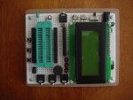
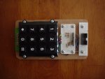
Serial Keypad

armagon29

New Member
Dear All:

I’m try to do a serial-keypad experiment using PICAXE 18X and a keypad, I need to capture and put into PICAXE one external variable introduced by the keypad and sent to other PICAXE with SEROUT command, but it woks in the simulator, but when I try to use it in the protoboard it doesn’t work, I check and re-check all connection and everything is OK, may the code has an error could someone help me to check the code please

Thanks

ARMAGON29
 

Attachments

Technical

Technical Support
Staff member
For PICAXE-PICAXE communication you probably want
serout 6,N2400,(b0,b1,b2)
not
serout 6,N2400,(#b0,#b1,#b2)
 

westaust55

Moderator
Without my full research of you code, what exactly is your problem.

Technical has understood the problem to be in the PICAXE to PICAXE code
due to the line:
serout 6,N2400,(#b0,#b1,#b2)

but in looking at the top of the program you have the line:
serout 6,N2400,(254,1)

which looks like you are clearing an AXE033 LCD display.
so the line near the bottom of the code seems to just be displaying 3 numbers to your LCD


Is the problem:
1. reading the keypad?
2. comms with second PICAXE? (in which case there needs to be a SEROUT wwith a different pin number to the AXE033 display),
3. another problem?
 

armagon29

New Member
Dear All:

When 3 key of the keypad is press, the program most to send the number of keys pressed (pun in variables b0, b1 and b2) in serial format, and show in the LCD, but the main problem is, when the circuit is connected to the computer trough download cable (to download the code into PICAXE) it works excellent, but when I disconnect the cable, the circuit start to work alone, and nobody press any key, “mysteriously”
 

BeanieBots

Moderator
Works fine with cable but erratic without is a classic fault.
Usually means either the serin pin does not have the correct pull-down circuit or the reset pin is floating.
A stand alone PICAXE MUST have serin pulled low and reset pulled high.
 

armagon29

New Member
how to do that, "PICAXE MUST have serin pulled low and reset pulled high.", how conect and the resistor values?
 

westaust55

Moderator
Please look at Manual 1 page 25 which shows the exact minimum circuit that you need with the serin pin pulled low (to 0V) and the reset pin pulled high (to +5V) with resistors
 

armagon29

New Member
I checked the connection of download circuit and reset (as manual) and everything is ok, I think that the code still have an error, can someone help me to check the code, please ¡
 

westaust55

Moderator
Have had looked through your code and tested it in the PE simulator (as you have done) and cannot fault the code.

That you say it works while the cable to the PC is connected suggests the program is okay and it relates to a hardware (wiring) problem.
Could be a bad connection (eg dry joint).

What proto, starter or development board are you using for the picaxe?
Can you upload a good clear picture of the board/wiring. Someone might spot something in the photo.
 

tarzan

Senior Member
If you haven’t already had a look at the Keypad Lock.pdf in the projects folder I suggest that you do. Take note that the inputs are pulled low with 10K resistors. There should also be diodes on the outputs or use current limiting resistors. This is to protect the Picaxe against shorts when more than one button is pushed at the same time.
 

armagon29

New Member
Dear All:

See 3 photos of the board, but may you will re- created this experiment of course if you have a picaxe and a few coponents, the keypad could be changed by push buttond and make a real test!

the development board was made by me


westaust55

Moderator
awaiting the 3 photos you mention . . . . .

If you are having problems uploading:
1. The pictures should be in jpg format, not bmp (save in the right format with your picture viewer/editor or MS Paint)
2. use the paperclip icon at the top of the edit window to access the attachment managr to add the photos
 
Last edited:

armagon29

New Member
I dont know, why I can not send the photos, but I will try again, I think that the problem is the code, not the hardware
 

tarzan

Senior Member
Keypad

I’m not sure if you have your columns and rows correct. I have mine with four rows and three columns it appears you have the opposite going bye your resistor layout. Should have three columns tied low via 10K resistors and four rows protected by diodes or resistors, I use 1K resistors.
 

Attachments

Last edited:

westaust55

Moderator
From the photo, the four resistor look like they have the colours brown black & yellow = 100 kOhm.

The other three resistors appear to be brown black & red = 1 kOhm.

Looks like there could be a couple of solder bridges across the keypad terminals as well.
If they are bridges, that would at least give wrong input data if not cause other problems/faults.

Really need to know which is which. CAN you upload a circuit diagram (aka schematic) ?

My keypad has 4.7 kOhm resistor for the columns to pull-down to 0V and 330 Ohm resistors for the rows going into the IC.

The values that Tarzan states (10k and 1k respectively) would certainly also be okay.


armagon29’s code is based on putting 4 line high (one at a time) and looking at 3 inputs so same context as Tarzan’s code.
But really need to look at a circuit diagram to see if the resistors are used correctly.
 
Last edited:

manuka

Senior Member
Having got this far, I guess you probably don't want to know about the "poor man's numeric keypad" approach do you? Aha- thought you'd weaken!

"Infra..." features on PICAXE-08Ms have near revolutionised simple IR sending & receiving, & even serial data can be sent this way. Naturally the range is pretty LOS, but for keypad use you'll normally be nearby anyway. Hence just use a cheap SONY style TV remote, whose keyed values are read with a PICAXE-08M via a Vishay style TSOP4838 3 terminal IR device. Easy! You can often now pick up universal remotes for ~US$5 (= cheaper than keypads!) in coin stores. Such an IR approach is usually more reliable than a R matrix keypad I've found too, as unbounced switch contacts on a wired version may give false triggering.

Fellow Kiwi Andrew "BrightSparK" has run with IR for all manner of PICAXE control- see the 4 stage light dimmer =>http://picasaweb.google.com/picaxe/Data#5238680486295630402 - you have to love the drawing pin switch contacts! (Usefully their shafts fit nicely on a breadboard)

Tarzan: Great work on that super neatly wired breadboard -you put my humble efforts to shame!
 
Last edited:

armagon29

New Member
Dear All:

I changed the resistors for diodes, and pull-down all pin no used, and the board works excelents, It is incredible that simple

Thanks for youl help
 

InvaderZim

Senior Member
Manuka, I see that the infrain command requires the picaxe to wait until a command is received; do you have a small axe just doing infrain, and a 2nd axe doing the rest of your program? Or am I missing something?
 

manuka

Senior Member
Of course using a 2nd PICAXE depends on your overall need/budget/circuit footprint- see a IR based "Core Duo" approach => http://picaxe.orconhosting.net.nz/duo08m2.jpg , with schematic => http://picaxe.orconhosting.net.nz/duo08m.gif. One 08M here is the "sensor", while the other the "doer".
Code:
'IRSENSE.BAS for Picaxe-08M, supporting April 2007 SiChip article
'Uses 2x 08Ms,one sensing & the other a doing Picaxe.See companion
'program (IRDO) & duo layout => www.picaxe.orcon.net.nz/duo.jpg
'Via => stan.swan@gmail.com  27th Feb. 2007
 
irsense:	
infrain2               		'waits endlessly until IR data received
 if infra >9 then error 	'detects non numeric IR remote key push
  high 4:pause 100      	'pin set high alerts 'doer' 08M data RTS
   sound 2,(100,10)      	'Piezo + parallel LED key press confirm 
  serout 4,t2400,(#infra)	'send IR key value as 'infra' (a.k.a. b13)
 low 4				'handshake pin set low for 'doer' Picaxe
goto irsense			'loop for further IR remote key presses

error:
sound 2,(60,5,0,5,60,5,0,5,60,5,0,5,60,5,0,5) 'fruity wrong key alert
goto irsense

'IRDO.BAS for Picaxe-08M supporting April 2007 SiChip article
'Uses 2x 08Ms,one sensing & the other a doing Picaxe.See companion
'program (IRSENSE) & duo layout => www.picaxe.orcon.net.nz/duo.jpg
'The received IR data values could be used in many ways, perhaps as
'program variables,or actioned under SEROUT for LCD display etc. 
'Via => stan.swan@gmail.com  27th Feb. 2007

irdo:					
if pin4=1 then serial  		'RTS alert for serin to accept data
 high 2:pause 100			'Sample ongoing activity-LED flashing
 low 2:pause 100 			'here but could be any Picaxe action
goto irdo				'loop until RTS pin 4 detected high
  

serial:
serin 4,t2400,#infra		'Accept serial data pin 4 ('infra'=b13)
 b12=infra+1			'Align IR remote keys & 'infra' values
  if b12=10 then zero		'Test for '0' key which shows as '10'
 sertxd (#b12,13,10)		'Use F8 to display IR remote key pressed
goto irdo

zero:
b12=0					'Ensure '10' key shows as '0'	
  sertxd (#b12,13,10)		'Display on Editor's F8 terminal program
goto irdo
 
Last edited:
Top