Looking for RGB LEDs in Australia

westaust55

Moderator
Does anyone know of an Australian source of R-G-B LED’s in 3mm or 5mm suitable for panel mounting (ie not SMD type) at a good price?
Looking firstly to buy locally due to falling AUD.

I am looking to build an 8 x 8 RGB LED display module for experimenting purposes. Considering to control the array using either 4 x 74HC595’s or some i2c IO Expanders.

Farnell in Australia want AUD$13.10 + P&P and only have a few in stock.
Dick Smith has them at AUD $3ea (far better) but only in some stores.
Jaycar has Tri-colour (Red, Green, Orange) LEDs in 3mm and 5mm at around AUD$0.75 & AUD$0.80 ea. Far better pricing but not R-G-B
Found a website for LEDsales in Victoria who indicate around $1.00ea but no phone number (on website or whitepages.com) and emails keep bouncing. Anyone know if they still in business?
 
Last edited:

BeanieBots

Moderator
LEDsales is changing! LEDsales is now moving away from most Chinese made LED products as the quality is just too variable.
Maybe they left it too late.
"Beyjing specials" have been the downfall of many suppliers.
 

westaust55

Moderator
Thanks all and in partticular the sender of a PM.

It has now been identifed that LEDsales are still in business albeit that they seem to like internet business. They do have (and answer) a phone and gave me their email address.

However, in view of BB's comment maybe I should order a few spares.
 
I am looking to build an 8 x 8 RGB LED display module for experimenting purposes. Considering to control the arrive using either 4 x 74HC595’s or some i2c IO Expanders.
Both NXP (PCA9635) and TI have I2C devices that include 16 bit led drivers with individual bit PWM. Should get full color with a device on each of the RGB channels (1/4 multiplex?). They are common anode devices, which could influence your choice of RGB leds.
 

westaust55

Moderator
i2c vs serout speed comparison

Following on from Nickelflipper's suggestion about i2c based LED drivers, I took a look at the data sheets for a few makes and types. They are available in various "widths" but the 8-bit and 16-bit were most likely to be useful.

All IC I located were, as NickelFlipper, suggested, for common anode LEDs. One potential problem – could not quickly locate any of these IC in Australia.

But, nevertheless, an email to LEDsales about Common Anode LED's in lieu of the Common Cathode LED's I had initially enquired about.

200 Common Cathode 5mm RGB LED's in stock at AUD1-00 each :)
but only 44 Common Anode 5mm RGD LED's in stock and unsure when he will (a) obtain more, and (b) what the new price will be with falling Aust Dollar :(

However I am looking for 64 plus a few spares.

As I am not really looking for all the fancy PWM and flashing capabilities of many of the LED driver chips thought arose whether there a significant difference between i2c and serial comms so decided I might beat Tiscando on a few more (unofficial) timings for i2c versus serout comms speeds.

With and 8 x 8 matrix of RGB LED’s that will look electrically like a 24 col x 8 row matrix. I will need to output 4 bytes (32 bits) of data per row of LED’s

Using a very simple test strategy employed.
Running PICAXE 40X1 at 4MHz then at 8MHz
firstly with an empty FOR ... NEXT loop 50,000 time for base timing
then run with some maths and the data transfer using first i2c then serout commands.
Included some basic math/variable assignments as they will always be necessary (okay it does not give exact time just for one instruction comms instruction) but for what I want to know, good enough.

The i2c code:
Code:
For counter = 1 to 50000
         temp0 = temp0 + 1
         temp1 = temp0
         temp2 = temp0
         temp3 = temp0
         HI2COUT [expand_0], (temp0)
         HI2COUT [expand_1], (temp1)
         HI2COUT [expand_2], (temp2)
         HI2COUT [expand_3], (temp3)
       NEXT Counter
The Serout code:
Code:
For counter = 1 to 50000
         temp0 = temp0 + 1
         temp1 = temp0
         temp2 = temp0
         temp3 = temp0
         shiftout clock,serdata,msb_1st,(temp0, temp1, temp2, temp3)
	   pulsout latch,5  
       NEXT Counter
Results extrapolated for 8 rows of LED’s (see attached sheet):

4 Mhz using serial will see around 16 scans per sec
4 Mhz using i2c will see around 24 scans per sec
8 Mhz using serial will see around 28 scans per sec
8 Mhz using i2c will see around 47 scans per sec

So while a bit theoretical and final scans rates will certainly prove to be slower with more maths inside the FOR NEXT loops, it certainly indicates that i2c is the way to go to reduce flicker.
 

Attachments

All IC I located were, as NickelFlipper, suggested, for common anode LEDs. One potential problem – could not quickly locate any of these IC in Australia.
They show up in stock at Mouser and Digikey here in the states. The Newark (Farnell) site doesn't seem to stock the NXP parts, but does have the TI tlc5941. The TI part is bit complicated for my taste.

Re-entered my location, as it seems to have slipped off the profile.

Someday hope to do a RGB display like what you are doing. Even with mono color leds, the bit addressable PWM can do some crazy effects. Do you have access to SSOP to DIP adapter boards? You can PM me if you want me check on things for you.

With a paint program like mtPaint, you can draw a bit/pixel sized array. A corresponding RGB decimal value is given for each color.
 

westaust55

Moderator
They show up in stock at Mouser and Digikey here in the states. The Newark (Farnell) site doesn't seem to stock the NXP parts, but does have the TI tlc5941. The TI part is bit complicated for my taste.

Re-entered my location, as it seems to have slipped off the profile.

Someday hope to do a RGB display like what you are doing. Even with mono color leds, the bit addressable PWM can do some crazy effects. Do you have access to SSOP to DIP adapter boards? You can PM me if you want me check on things for you.

With a paint program like mtPaint, you can draw a bit/pixel sized array. A corresponding RGB decimal value is given for each color.

Thanks Nickelflipper.
albeit from down under your forum name does give an indication of your location. :)

My experience with the likes of Mouser is the high cost of the shipping charges - would double the cost of my project.

I have a quantity of SOIP8 to DIP8 adapters and could no doubt find larger sizes as required.

I have tended to use Excel with underlying maths to calculate the values (typically in hex) for a number of graphic projects to date like creating new fonts and images that are not readily calculated using BASIC maths.

For my current project I will stick with the i2c IO expanders I have at hand or consider some MCP23016/17 16-bit expanders where two consecutive bytes can be writen to the two output ports.

Maybe start looking at some more dedicated LED drivers with PWM and flashing etc at a later date.

Again thanks for your comments.
 

westaust55

Moderator
LEDsales in Victoria

Thanks centrex.

Yes they are still in business but the email address on their website,
namely: admin@LEDsales.com.au
is no longer working - give that one to the spammers :).

Lance gave me a "new" email address (which I will not disclose here as differnt again from one below) but if you place an order you get a different email address being:

orders at LEDsales dot com dot au

so people could use this if they need to get a message or enquiry to Lance.
 
Last edited:

westaust55

Moderator
RGB LED display calculator

With a bundle of RGB LED's now on the way from LEDsales, I had a trial tonight to create a calculator in Excel that would enable me to calculate the four bytes of data required for each row of LED's.

Attached is a version of that calculator together with a test pattern.
Possibly due to limitation in my knowledge of Excel could not create nice solid blocks of colour for all 8 colours and instead had to use odd shaped chunky graphics to permit me to display the eight basic colours (from straight on of for each colour) representing each LEDs output.

For those who may wish to have a "play",
use the number "1" in the top left region to indicate which LED colours are on in each row. "0' or clear is off and any other value/character may give erroneous results.

rough representation of the expected pattern is given at the top right.

The values of the data in hexadecimal to go into EEPROM statements or elsewhere are given at the bottom left.

To use the file download and change the file extension to .xls
 

Attachments

Last edited:

BCJKiwi

Senior Member
Westy,

Have tweaked the SS a bit.

However two comments about the attached;
1. there is a macro to set the cell colour and the text colour based on the value in the cell but I can't get it to work! So have resorted to the RGB indicator.
2. Since you locked/protected/whatever your SS, can't see what you are doing in the lower section so have not included code for that part.

Have tweak!
 

Attachments

westaust55

Moderator
Hi BCJKiwi,

I have tonight downloaded from the forum onto a friends PC and my spreadsheet works okay here (Excel 2003).

I am using the same conditional format as you to set colours.
No macros but a few formula in the black areas (with black text to hide them) to calculate the values 0 to 7 for the greater number of colours rather than 3 per LED "cell". That is why I have the chunky graphics as there is a limit of 3 colours per spreadsheet cell and each LED is in fact represented by 9 small cells.

You should now be able to see what I am doing inside mine in previous post.
 

westaust55

Moderator
RGB LED's have arrived

My bundle of RGB LED’s arrived from LEDsales (Vic, Aust).

LEDsales had emailed me a datasheet and the email included the comment to check the configuration.
Sure enough a test with the multimeter found the pinout did not match the datasheet. Nothing major but I guess something to be aware of with RGB LED’s out of China that pin out standrds are not necessarily consistent.

Code:
Pin    Datasheet       Actual
1        Blue             Red 
2        Common       Common
3        Red             Blue 
4        Green          Green
While waiting, I had done some calcs in Excel to determine approx values for the resistors I needed in series with each LED colour for roughly equal intensity. A few tests on a bread board using the intended interface LED driving transistors found some minor adjustments so that one colour did not “wash” another out when using two LED segments for a secondary colour. (eg Red+Blue to get a pink and Red+Green to get a yellow). See attached calc sheet.

I am using the interface transistors for a couple reasons:
1. To enable multiplexing with up to 8 RGB LEDs in a row so 24 cathodes controlled with one Output
2. While an IO Expander output can source the current to drive the Anode side of one LED, just in case of a future programming error :eek:, bringing on multiple rows simultaneously that may/will overload an output I have included interface transistors from the start.

While I will start with an 8 x 8 matrix, the box size will permit me to expand to an 8 x 12 matrix at a later date with minimal mods.
So while awaiting my MCP 23017 IO expanders, will start to assemble the rest of the module circuit next week.
 

Attachments

Last edited:

BeanieBots

Moderator
If they came from China and the pinout does not match the datasheet, then I doubt the datasheet has any relation to the LED at all.
Like most documentation from China, which includes CE Marking, RoHS compliance and others, it's nothing more than a piece of paper shipped with the component. There is no other connection.
My advice is to put that datasheet in the bin before you fall into the trap of thinking you have reliable numbers for If, Vf, mCd and colour spectrum.
 

moxhamj

New Member
I guess what you are doing with the LEDs is white balancing. When doing knee endoscopies, and other scopes, one of the setup tasks pre-op is to white balance the camera. Usually the 'white' object is a bit of gauze.

Hopefully with the leds you will only need to do this once, and hopefully the leds track in a linear way once you have determined the white balance resistors. If not, it might be something that needs to be tweaked in code.

It sounds an interesting project. Keep us posted!
 

westaust55

Moderator
If they came from China and the pinout does not match the datasheet, then I doubt the datasheet has any relation to the LED at all.
Like most documentation from China, which includes CE Marking, RoHS compliance and others, it's nothing more than a piece of paper shipped with the component. There is no other connection.
My advice is to put that datasheet in the bin before you fall into the trap of thinking you have reliable numbers for If, Vf, mCd and colour spectrum.

Hi BB,

Yes I had basically done just that.

I measured the Vf for each of the LED elements and they are all lower than the "stated" values and entered those into tmy spreadsheet to get a first determination on series resistors. The supplied sheet claimed Vf as Red =2.0V, B & G as 3.5V. As mentioned the actual values are lower.

Then a bit of fine tuning for colour balance (by eye only) so one LED colour does not "wash" out another.
 
Last edited:

westaust55

Moderator
I guess what you are doing with the LEDs is white balancing. When doing knee endoscopies, and other scopes, one of the setup tasks pre-op is to white balance the camera. Usually the 'white' object is a bit of gauze.

Hopefully with the leds you will only need to do this once, and hopefully the leds track in a linear way once you have determined the white balance resistors. If not, it might be something that needs to be tweaked in code.

It sounds an interesting project. Keep us posted!
As the first pass, I am using 2 x MCP23017 i2c IO Expanders to get 32 outputs for multiplex control the 64 RGB Leds (=192 LED elements).
This will give me just 2^3 = 8 different colours.
Do not think there would be much ability to provide on the fly colour variation without slowing down the scan rate.

Certainly not impossible to change to some PWM type LED drivers at a later date to get more colour variation. With those, some colour correction could be done in software as you suggest, but think more time senting control data to the LED driver chips which will again reduce the scane rate resulting in more display "flicker".

Will certainly post more details as the project progresses . . . . .
 

westaust55

Moderator
Thanks MyC.

I'll console myself with the fact that those are US dollars and by the time I paid postage and got it here to Oz, the saving would not be that great.

My initial 8x8 array will be the same size with provision to expand to 12 x 8.

At least half of the fun is building these modules form scratch myself.
 

westaust55

Moderator
MCP23017 i2c IO Expanders

Since I have been asked (in PM’s) where I bought the MCP23017’s from, I can advise that I have purchased them from Futurlec.
See www.futurlec.com.au. I have used Futurlec in the past – good pricing, cheap postage and relatively fast.

They have a “shop front” of sorts in Sydney but the goods are dispatched out of a warehouse in Thailand.
But with postage at just AUD$4 cannot be beaten.
 

BCJKiwi

Senior Member
Also found Futurlec good to deal with.

You can also order off the futurlec.com site - some minor differences in products and prices - shipment from the same place in Thailand.

I currently favour futurlec.com
 

westaust55

Moderator
Hmmm,
Futurlec have on this occassion let me down :(
Ordered some MCP23017 IO Expanders at the same time I ordered my RGB LED's.

LED's arrived from Victoria in about 2 day but after 2 weeks no sign of the IC's.

Futurelec webset indicated the order had not been dispatched so send of an email. Response today to inform me the sought IC's are out of stock until Jan 2009. :(

Now 3 weeks ago and even today, their website indicates these chips are in stock.

Just Checked with Farnell in Aust and they are also out of stock now for the SDIP chips.

So for now, my multi-RGB dsplay module is on hold :rolleyes:
 

tiscando

Senior Member
Westy, If you can get spi chips and you can't get the i2c chips, then by serout, do you mean rs232 or spi? I presume spi, so do you know there are SPI shift register LED drivers e.g. the stp16cl596 and the stp16*05? I presume that a 1mhz clock rate (the maximum for the hspi bus) would refresh a chain of 8 stp16cl596 16-bit led drivers in <~20ms. Try:

Code:
setfreq m8
hspisetup {whatever the mode}, spimedium (see note1)
...
...
hspiout (...)
...
note1: when I looked at the spi speed constants, spifast is 0, spimedium is 1, and spislow is 2, and when I tried spifast, the picaxe 28x1 stalled and restarted after 2 seconds, whereas the spimedium worked.
 

westaust55

Moderator
Thanks for the suggestions tiscando.
Somehow missed your post until this morning.

At the moment I am sticking with the i2c approach for multiplexing.

When I did some comparative tests of i2c versus SHIFTOUT (aka SPIOUT) command on a 40X1, the i2c gave a good speed improvement. And that was with slow i2c devices at the time.

One thing about this forum is the help between members. I have in the past bought a few extra parts and passed a few onto others and now BCJKiwi has offered me the use of some MCP23017’s he currently has spare to help me “keep feeding my addiction” A BIG thanks there to BCJ.
 

westaust55

Moderator
RGB LED MAtrix display

Assembly of my RGB LED matrix and controller board has finally reached completion and ready for software testing.

Attached are a few photos of the hardware side.

Used a piggy back approaach to the i2c controller board so that it will fit into the box with the LED's on the lid.

Mounting TO92 transistors at 0.1" (2.5mm) spacing is not really idea but only way to go for a compact assembly.
 

Attachments

westaust55

Moderator
8x8 RGB LED Matrix driver software

Wrote some code this evening and got my RGB LED matrix up and running.

Will draw up a tidy schematic and upload along with some pics soon.

Running at 8MHz the pattern is clearly visible but there is still some flicker.
An external resonator at 16MHz would be better.

Code:
; =================================================
;   File....... RGB 8x8 LED Matrix Test
;   Purpose.... test operation of the set of an 8x8 RGB LED matrix via i2c comms 
;   Author..... Westaust55
;   E-mail.....
;   Started.... 07-01-2009
;   Updated.... DD-MM-YYYY
;  ===============================================
;
; -----[ Program Description ]---------------------------------------------
;
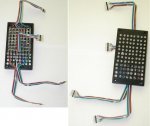
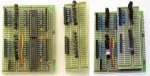
; A program to test operation of the 8 x 8 matrix of RGB LEDs as a 
; visual multicolour panel using i2c comms and MCP23017 IO Expanders
;
; -----[ Revision History ]------------------------------------------------
; First coding
; 
;
; -----[ I/O Definitions ]-------------------------------------------------
;
;
; -----[ i2c Devices ]-------------------------------------------------------
;

;
; IO EXPANDERS
SYMBOL expand_0 = %01000000  ; %0100 = Chip ID, 000 = Addr 0 - For the 8 Red LED's
SYMBOL expand_1 = %01000010  ;                , 001 = Addr 1 - For Keypad Shift LED
SYMBOL expand_6 = %01001100  ;                , 110 = Addr 6 - For RGB LED matrix red and green
SYMBOL expand_7 = %01001110  ;                , 111 = Addr 7 - For RGB LED matrix blue and common
;
;

; -----[ EEPROM Data ]-----------------------------------------------------
;
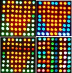
; dataset 1 = Red heart no other colours
EEPROM ($99,$FF,$FF,$01)
EEPROM ($00,$FF,$FF,$02)  
EEPROM ($00,$FF,$FF,$04)   
EEPROM ($81,$FF,$FF,$08)   
EEPROM ($81,$FF,$FF,$10)   
EEPROM ($C3,$FF,$FF,$20)   
EEPROM ($C3,$FF,$FF,$40)   
EEPROM ($E7,$FF,$FF,$80) 
;
; dataset 2 = red heart with green surround
EEPROM ($99,$66,$FF,$01)
EEPROM ($00,$FF,$FF,$02)  
EEPROM ($00,$FF,$FF,$04)   
EEPROM ($81,$7E,$FF,$08)   
EEPROM ($81,$7E,$FF,$10)   
EEPROM ($C3,$3C,$FF,$20)   
EEPROM ($C3,$3C,$FF,$40)   
EEPROM ($E7,$18,$FF,$80)  
;
; dataset 3 = red heart with blue surround
EEPROM ($99,$FF,$66,$01)
EEPROM ($00,$FF,$FF,$02)  
EEPROM ($00,$FF,$FF,$04)   
EEPROM ($81,$FF,$7E,$08)   
EEPROM ($81,$FF,$7E,$10)   
EEPROM ($C3,$FF,$3C,$20)   
EEPROM ($C3,$FF,$3C,$40)   
EEPROM ($E7,$FF,$18,$80)
    
;
; -----[ Initialization ]--------------------------------------------------
;
Init:   setfreq m8
        HI2CSETUP i2cmaster, expand_7, i2cslow, i2cbyte
        HI2COUT [expand_6], 0,  ($00,$00)    'IODIRA,IODIRB set port direction register to output
        HI2COUT [expand_6], $12,(%11111111,%11111111) 'turn off Red & Green LEDs (output high)
        HI2COUT [expand_7], 0,  ($00,$00)    'IODIRA,IODIRB set port direction register to output
        HI2COUT [expand_7], $12,(%00000000,%11111111) 'turn off Row dirve (low) andBlue LEDs (high)
        
;
;
; -----[ Program Code ]----------------------------------------------------
;
Main:	  HI2CSETUP i2cmaster, expand_1, i2cslow, i2cbyte ; Set up for 9th LED
        HI2COUT (0) ; SHIFT LED off
        PAUSE 500
        HI2COUT (1) ; SHIFT LED on - just blink LED on and off
        PAUSE 1000
        HI2COUT (0) ; SHIFT LED off
        PAUSE 500
        HI2CSETUP  i2cmaster, expand_0, i2cslow, i2cbyte ; Set up for set of 8 LEDs
        HI2COUT (255) ; turn on all LEDs for 1.5 second
        PAUSE 1500
        HI2COUT (0)
        pause 1000

; the above line of code are just to turn of the LED's for the bargraph and keypad shift key
; these LED's use positive logic (1 = ON, 0 = OFF) done by adding a transistor to the expander outputs.
;
;
        
REDheart: 
       FOR b2 = 1 TO 100
         FOR b0 = 0 TO 7            ; for 8 rows of data (8 x 8 marix display used)
           b1 = b0 * 4              ; set pointer for next 4 bytes
           READ b1, b6, b7, b8, b9  ; Read each line of data to send to the display
           GOSUB shwpattn           ; now display the correct LED pattern
         NEXT b0
                             
       NEXT b2
Greensur:        
        FOR b2 = 1 TO 100
         FOR b0 = 0 TO 7            ; for 8 rows of data (8 x 8 marix display used)
           b1 = b0 * 4 + 32         ; set pointer for next 4 bytes
           READ b1, b6, b7, b8, b9  ; Read each line of data to send to the display
           GOSUB shwpattn           ; now display the correct LED pattern
         NEXT b0
                             
       NEXT b2
Bluesur:        
        FOR b2 = 1 TO 100
         FOR b0 = 0 TO 7            ; for 8 rows of data (8 x 8 marix display used)
           b1 = b0 * 4 + 64         ; set pointer for next 4 bytes
           READ b1, b6, b7, b8, b9  ; Read each line of data to send to the display
           GOSUB shwpattn           ; now display the correct LED pattern
         NEXT b0
                             
       NEXT b2        
finish:        
       HI2COUT [expand_7], $12,($00) ; turn off LED row drive
        
        
       END
;
; -----[ Subroutines ]----------------------------
;
shwpattn:              ; pattern for full circle on LED indicator
          HI2COUT [expand_7], $12,($00) ; turn off LED row drive to prevent brief display of previous row on the new row of LED's
          
          HI2COUT [expand_6], $12,(b7,b6) ; green and red columns
          HI2COUT [expand_7], $12,(b9,b8) ; row drive and blue column
          
          PAUSE 10
          RETURN
;
; =================================================
;      THE END
; =================================================
 
Last edited:

westaust55

Moderator
RGB LED 8x8 Matrix.

As promised a few pics of the end results.

Will upload a schematic another day . . .

Due to the scanning effect down the rows, as can be seen, really needs a slow photo ASA speed and a tripod (not hand held) to get a better shot.
 

Attachments

hippy

Technical Support
Staff member
Looks good. To improve performance and reduce flicker you can probably minimise the maths done within the FOR-NEXT loops -

Code:
REDheart: 
  FOR b2 = 1 TO 100
    FOR b0 = 0 TO 7
      b1 = b0 * 4
      READ b1, b6, b7, b8, b9
      GOSUB shwpattn
    NEXT b0                             
  NEXT b2
Becomes -

Code:
REDheart: 
  FOR b2 = 1 TO 100
    b1 = 0
    FOR b0 = 0 TO 7
       READ b1, b6 : b1=b1+1
       READ b1, b7 : b1=b1+1
       READ b1, b8 : b1=b1+1
       READ b1, b9 : b1=b1+1
       GOSUB shwpattn
    NEXT b0                             
  NEXT b2
You may ( not tested ) also get improvement using DO-LOOP instead of FOR-NEXT -

Code:
REDheart: 
  b2 = 1
  DO
    b0 = 0
    b1 = 0
    DO
      READ b1, b6 : b1=b1+1
      READ b1, b7 : b1=b1+1
      READ b1, b8 : b1=b1+1
      READ b1, b9 : b1=b1+1
      GOSUB shwpattn
      b0 = b0+1
    LOOP WHILE b0 <= 7                  
    b2 = b2+1
  LOOP WHILE b2 <= 100
Decreasing to zero ( or one ) DO-WHILE should also be slightly quicker than increasing if usable -

Code:
  FOR b0 = 1 TO 100
    GOSUB something
  NEXT
becomes

Code:
  b0 = 99
  DO
    GOSUB something
    b0 = b0 - 1
  LOOP WHILE b0 <> 0
 
Last edited:

westaust55

Moderator
driving a RGB LED matrix

Tried a few different programmnig structures to see what speed improviement could be found.

First increased to loops from 100 to 200 for each section and reduced the PICAXE speed, so the time differences would be more identifiable.

Results were:

1. Original code:

~ 7 mins 11 sec

2. The original code used i2cslow keywords so changed these to i2cfast.
No change in speed/execution time detected.


3. Changed the code to remove the multiplication from within the FOR...NEXT loops and use only addditions with less maths in the loop.

6 min 46 sec = 6% reduction in execution time


4. Changed the code structure to use a DO...LOOP UNTIL in place of the FOR...NEXT.
5 min 51 sec = 19% reduction in execution (over original time)


In summary, the DO...LOOP construct with addition instead of multiplication achieve a better speed.

Flicker is still visible but in theory it sould be visually better at the faster speed. Might purchase a 16MHz resonator to use with my 40X1 and see what improvement is visual display is achieved.
 
Top