Erm, voltage regulator exploded

Before you ask, no, that was not the intention.

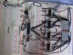
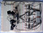
Basically i couldnt get the dual layer PCB routed correctly for this digital clock idea, so i resorted to the rather less elegant solution of building it on breadboard.

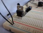
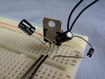
So anyway, yesterday i turn it on, the 7805 voltage regulator get's very hot, very quickly and gives off a small trail of smoke, so i unplug everything asap and have a look over the board for shorts and anything obvious, nothing, except the possiblity that i may have connected ground of the supply, to the output pin, instead of ground.

So i turn it on again, and after a few seconds, bang! flash of orange, big sound and the whole chip splits open :(

Does anyone know what could cause such a big problem that quickly? neither of the two cap's around it were damaged, and i didnt put a new program on the picaxe so none of the led's were drawing current and i've seen these things heat up due to short circuits and be fine. The datasheet even describes them as 'virtually indestructible'

The breadboard is semi-neat so i could post pictures of it if that would help, i was just wondering if anyone had done the same and knew how it happened. I have another 7805 but dont really want to try it until i know roughly what happened. Also, i was using a 26v DC supply, rated for 1.5A, a little high but within spec for the Vreg. (And the spare Vreg functioned just fine on this supply, it's a new one that went wrong, so i assume that points to a wiring mistake)
 

BeanieBots

Moderator
There are hundreds of varieties of 7805 but most of them have thermal shutdown. So, it very likely that you have a wiring fault with regulator itself rather than a short or similar on the regulated line.
With the writing on top, legs towards you, the pinout is in-gnd-out.
It's been said countless times, and I'll say it again, use a current limited power supply for prototype work. It would have saved you a regulator and possibly your breadboard.
26v input is rather high for 5v out. The thermal resistance of a T0-220 package is about 65deg/W. A typical 7805 will shut down at 125deg but you really shouldn't run any semiconductor at > 70C. Assume an ambient of 25C, that gives you 45degs to play with. That limits the power to 0.7W.
With 26v input and 5v output, you are dropping 21v across the regulator which means the maximum current it can handle would be only 33mA.:eek:
I think you will agree that is not very much.

Anyway, fix your wiring problem and then we can worry about your heatsinking problems.

Please post a picture, it should be quite obvious.
 

Dippy

Moderator
I can't explain why it blew up, but I often wonder about these claims of "protection" and "virtually indestructible".
I get the feeling its somewhat conditional and really shouldn't be in the headline description without qualifiation.
Maybe this is something you should take up with the Manufacturer?
(Most people are too scared to ask the Big Boys.. do it and see what the answer is)

There are a couple of things to note though beyond the 'headline' description of a device.
First power dissipation.
You are doing a BIG voltage drop and that usually results in a heap of watts.
You are dropping from 26V to 5V. 21Volts.
If you were using an Amp. Thats 26Watts in and 5 watts out. Where does the 21watts go? HEAT. Thats a lot of heat and your little thing would melt in a few seconds.
You must be CAREFUL about big voltage drops when using significant current.
(This is where Switched Mode eats linear in many apps... but that's another subject which I'm sure people will digress onto).

In your circuit you shouldn't be using very much current, however, with that volts drop you will still need a heatsink. How much? Size? Do your calcs.

testing:
First, remove the 7805 corpse and bury it with full military honours.
I would start off by putting a Multimeter (Ohms setting) onto the 5V in of your circuit . That's the obvious first step to check for S/Cs. Note that any initial and brief apparent short may just be capcitors charging up.
If nothing shows up , and this depends on your Multimeter testing voltage, then it could be a semiconductor related short e.g. a diode reversed or something.
Anyway, it's then a matter of looking for obvious wiring errors and component misplacings.
if that checks out OK then consider component failure.
Again time consuming and even the best photo you can post won't help us with this bit.

Are you using big electrolytics? Are they the right way round?
Time for you to investigate. I assume you have a multimeter?

PS. A supply of that size is far too big and butch for prototyping. You REALLY should try out the basics using the Stan Battery setup. Or get your folks to buy you a current limited power supply for an early Christmas present.

PPS. Post crossed with BB, read his calcs re power dissipation. Sounds like you're going to have to dig out your calculator and read up a bit. I take it you're an electronics newbie?
 
Last edited:

evanh

Senior Member
Agreed with all above advice. I'll add one more thing. Try the replacement with a short on the output again. I think you'll find that it will smoke also.

26+ volts dropped at full short-circuit current with not heat-sink is just too extreme a condition for the thermal limiting to function in.


Evan
 
If you had the device the wrong way round (assuming you used a T0-92 package) at 26v that would still output power but i think it would blow it to bits. (Been there, but only at 5 volts i had the silk the wrong way) so as Dippy says - its a lot of power - that extra juice has to go somewhere.

A diode such as IN418 before the regulator would also help save the reg.

A 6v battery pack is always the way to go if you don't have a bench supply. Things slowly cook on low heat, that way you can sometimes save these devices from a full meltdown.
 

Dippy

Moderator
"26+ volts dropped at full short-circuit current with not heat-sink is just too extreme a condition for the thermal limiting to function in."

- that's useful info Evan. Have you got some additional Data on these devices that you can share?

So how does the thermal "Protection" work and what are the limiting factors?

Rhetorical1: And why, on the three Data Sheets that I looked at, doesn't it get a mention as this is chuffing important?

Rhetorical2: Why are we too scared to ask the Manufactuer's for an explanation? (I bet no-one will ask... you go first.)
 

westaust55

Moderator
Voltage Regulators and heat SInks

here is some data that demonstates what you can do with regulators and various type of heat sink.

Could put the spreadsheet up but excel sheets not allowed.

The attached pic is of a small TO-220 type heat sink that I frequently use.

A TO-92 type regulator is rated for 100mA but limiting the junction temp to 70 deg C drops that rating to around 50mA with a 4V drop across the regulator.


EDIT:
Some data on the heatsink: Pre-drilled to take a single flat-pack semiconductor. Mounting pins are 2.15mm in diameter and 3mm long. Heatsink is black anodised, and is 25mm high, 16mm wide, with 16mm long fins. Thermal Resistance: 18°C⁄W
from DSE (Australia) Cat No . H3490
 

Attachments

Last edited:

Dippy

Moderator
Yes, I'm sure there are many useful on-line resources if you wish to calculate so I wouldn't worry about posting (or not) an excel file WA.

Maybe get Blue Eagle's shorts sorted first? And then we may even persuade hin to use a more suitable power supply and then do some heatsink calcs. No point suggesting a half-brick if he's going to use something smaller.
 

moxhamj

New Member
26V is way too high as already said lots of times.

I have had 5V regs running off 15V and almost shorted them and the thermal protection happily cycles in and out every 30 secs or so. But I also had a batch of cheapie 5V regs (back in the 80s so can't blame ebay), and these regs were 5V regs but they didn't have the thermal protection. They would then heat up and explode.

Do you have a 9V wall wart? If not, could you get one? And then if you want cheap and cheerful short circuit protection - run the wallwart 9V into a 5V reg, and put a 6V 500mA torch globe in series with the 5V output. If you short it, the worst that will happen is the globe lights up.
 

hippy

Technical Support
Staff member
I've had no problems with 7805's pushed to the limit; I use a 7805 plus diode in the common line to drop 13.8V SLA batteries to 6V at 2A for an old digital camera. That's heatsinked and makes for a convenient hand warmer ( sometimes hand burner ), thermal shutdown kicks in after about 15 minutes.

That's with the 7805 wired correctly and, as noted, if wired wrongly all bets are off; that's where I'd check first. 7805's are not equal so it could be poorer thermal shutdown or too much V and I too quickly.
 
Wow, loads of replys, thanks guys.

Beaniebots post is very interesting, i never thought about it like that, but it makes sense. (makes my realise that last year's school project was very close to the limit of the Vreg (9v supply, so 0.7/4=0.175A, and i measured it using 160mA)

Anyway, here's the pictures you wanted, hope it's not too messy, looks worse seeing it afresh from a distance lol. (btw, that diode is an IN4001)

PS: Yes, i am rather new to electronics so tend to overlook certain things (like this lol)
 

Attachments

Dippy

Moderator
Blimey, thats a woppa!

I'm not familiar with those types of breadboard so don't know whether the power lines are connected internally.

Asking for trouble having power supply + and - as both black.

Have you tried, as suggested, putting a multimeter (ohm setting) on the 5V side with the regulator removed?
- checking for obvious shorts across the +5 and ground?

Sorry, there's too much for my 5 minutes :)
I'll leave it to others.
 
Sorry, forgot about that. The result is there is a resistance of about 500k, which is about the same as the resistance between each of my hands, so i think we can rule out a direct short.
 

Dippy

Moderator
Are you sure about the polarity of the power to the regulator?
Two black wires...

OK, so no obvious direct short... though 500K ohms sounds suspiciously high though that may depend on the voltage of the resistance test probes I suppose.

So, disconnect the main boards from your new reg.
Double check Vin , Gnd , Vout connections.
What happens if you just have your regulator+caps Vout connected to an LED+1k res? i.e. a piddly load. Is there 5volts? Does reg get hot?

I think if its not something obvious then this could be a long job.
 
Shit, blew up the 100uF cap, bigger bang!

The led did light though, i guess it's time to chuck that supply in the bin and go for 4.5v batteries.

(in fact, looking at the cap, it is only rated for 10v, and was getting 26v, i guess that could be the problem, defo time to chuck that psu, dont like blowing stuff up)
 

westaust55

Moderator
From past experience and noting that you have long-ish leads on the capacitors near the 7805 what are inserted at a bit of an angle.
It is possible when leads are insered at an angle to result in a bridging or short between two adjacent breadboard holes inside the breadboard.

Been there ages ago - but luckily without damage

EDIT:
looking at the very first photo, you have two wires coming onto the breadboard.
One goes via the diode to the 7805 input terminal.
If the second is the 0V/ ground wire, where it the connection to the 7805 common (centre) terminal ?
You have two wires from common and the output terminal going to the next board. Is the 0V/ground being backfed from the main boards back to the breadboard with the 7805 on it?
 
Last edited:

Michael 2727

Senior Member
Safety Glasses may also be a good idea till you sort out your voltages/polarity etc, ;)

If that 100µF had been a 1000µF or bigger, your new nickname may have been Patch.
 

hippy

Technical Support
Staff member
With things exloding everywhere it is possible that you've also 'taken out' other things along the way, maybe even breadboard tracks.
 

Dippy

Moderator
Blowing up caps usually indicates incorrect polarity OR voltage rating is too low for application.
I suggest you have a long hard re-check of your polarities, your wiring and the component values.
For a 20 to 25volt supply you should really be using 35V capacitors or higher.
I think bedtime reading of Data Sheets is also in order as it sounds like you are a bit confused.
 
:( Dont i look the noob now lol

Ok, well i rekon the capacitor was purely down to voltage rating, 10v and it was getting 26v (odd it didnt explode the first time around though)

As you say, i know i may have taken out other stuff so i have decided that the psu i have is a no go and i'll just stick to batteries from here on in! I'll just have to hope that vreg still works as i only had two nd it's a bit of hassle to get more.


p.s after the first smoking vreg incident i did actually put on my glasses, even if they arent exactly massive safety ones ;)
 

BeanieBots

Moderator
Electrolytic caps have a finite life span no matter what voltage you run them at. Running them close to spec significantly reduces the life. Running over spec will work for a very short while as apposed to instant destruction.
(10uF,10v tantilum connected to 240v AC is fun but put your safety glasses on)

The one that catches many out is running them at excess current.
Consider a cap in a simple transformer, 4 diode bridge, smoothing cap configuration. When the diodes conduct, the cap charges, when they don't, the load discharges it. This happens at every polarity change of the mains and so it looks like fairly smooth DC but the cap is doing all the work. If it can't handle that current, it will eventually pop.

I know I'm a cynic but ever wondered how they make electrical goods which fail at almost the exact moment the warranty expires?
 

Dippy

Moderator
Remember the old saying: "A little learning/knowledge is a dangerous thing".

Blue Eagle: I suggest you put your glasses on BEFORE you construct your next circuit. There is a good reason why manufacturers write stuff on the tins you know :)

"Dont i look the noob now"
- Be like the old USSR; keep your mistakes a secret!
 

evanh

Senior Member
"26+ volts dropped at full short-circuit current with not heat-sink is just too extreme a condition for the thermal limiting to function in."

- that's useful info Evan. Have you got some additional Data on these devices that you can share?

So how does the thermal "Protection" work and what are the limiting factors?

Rhetorical1: And why, on the three Data Sheets that I looked at, doesn't it get a mention as this is chuffing important?

Rhetorical2: Why are we too scared to ask the Manufactuer's for an explanation? (I bet no-one will ask... you go first.)
Heh, Dippy, you are quite correct. The thermal limiting info is entirely non-existent. And, to be honest, I haven't actually tried cooking one myself. I may have been a bit bold in my statement. I hadn't considered the idea that some 78xx regulators don't have thermal limiting.

I reasoned it in my head that the internal limiting circuit is proportional in nature, rather than a state change. This would then be dependent on what those proportions are. I visualised that the current output would not completely turn off. Time for some experimenting of my own ...


Evan
 

westaust55

Moderator
voltage regulators

Looking at a 2005 National semiconductor 7805 datasheet, while the intro has all the nice warm fuzzy words about virtually indestructible, etc.

Deeper down in the application details there are words saying ALTHOUGH the regulators have over current and thermal protection, that they MUST NOT be operated at greater than 125°C

To me that reads that it is possible to achieve higher temperatures (without the aid of a blow torch) and thus let the smoke out. But in looking at several datasheets there is no indication of the response time of these protection circuits. That could be where the issue lies, in that a very rapid rise in temp is too fast for the protection circuit.
 

ptribbey

New Member
Ground connection?

Blue,
I don't see a ground connection from your power in, on the upper left, to the middle ground pin on the 7805.
To me, it sounds like you may have reversed polarity on the input of the 7805 to destroy it so rapidly.
Just lift one input wire and measure the wart output. Once that is verified, replace the wire and lift one output wire and measure the +5. If that checks out, run the positive side of the +5 through a 6 volt bulb to your circuit.
If the bulb lights bright, you have excessive current draw.
Paul
 

westaust55

Moderator
Blue,
I don't see a ground connection from your power in, on the upper left, to the middle ground pin on the 7805.
To me, it sounds like you may have reversed polarity on the input of the 7805 to destroy it so rapidly.
Just lift one input wire and measure the wart output. Once that is verified, replace the wire and lift one output wire and measure the +5. If that checks out, run the positive side of the +5 through a 6 volt bulb to your circuit.
If the bulb lights bright, you have excessive current draw.
Paul

Possible missing ground connection was covered at post 17 and Blue Eagle responded at post 18.
 

demonicpicaxeguy

Senior Member
I know I'm a cynic but ever wondered how they make electrical goods which fail at almost the exact moment the warranty expires?
i think there is some sort of timer built into most cheap dvd players which only allows them to actaully play dvds for a preset amount of hours, my only evidence to support this theory is the 13 dvd players i have purchased in only the last 2 years

it would be an interesting picaxe project to build a dvd timer
 

evanh

Senior Member
I worked it out. Thermal runaway wasn't the cause or the result of the failure. The regulator was already dead before it got hot. The flames were just the final stage of destruction.

And yes the thermal protection does work, even under these conditions. I just tested it with output shorted and input in increments up to 30 volts on the bench with no heatsink. :>

The problem is the old issue of back flow of current from the storage capacitor on the output side to the input side via the internals of the regulator. This is a known easy way to kill a regulator. The fix is to place a reverse bias diode across the input to output pins of the regulator. And I'll be the first to admit I don't usually bother with this protection in my circuits.

If that 10 volt capacitor wasn't failing this particular problem wouldn't have shown up.

The other easy way to kill a linear regulator like these is to over-voltage the input.


Evan
 

evanh

Senior Member
So there is a very good chance that 26 volts ended up on your 5 volt rail. :(

I usually do add a zenor/transorb to the power rails to prevent extreme over-voltages like this. That goes for the input of the regulator also, but with a decent amount of headroom for small surges.

If the zenor is hit hard it always fails short-circuit, which in turn pops the local fuse, protecting the downstream components.


Evan
 
- Be like the old USSR; keep your mistakes a secret!
Hehe, i like it!

Well if the 5v rail became 26v then everything is probably completely screwed so lets just hope thats not the case.

I'll try with 3x AA batteries (for 4.5v)......and without a voltage reg?
 

Dippy

Moderator
Without.

Oh, dear old Blue Eagle, please have a read of data sheets and online tutorials.
A 'traditional' regulator needs a certain amount of voltage headroom. That old dinosaur you're using will need 7 to 8 volts input to guarantee 5V out. See the Data Sheets referring to 'dropout' voltages. You will see some regulators are called Low Dropout, because they have a lower dropout. Some micropower regulators have dropouts in the tens/hundreds of millivolts.

Just be aware that a piddly battery pack can also smoke delicate semiconductors if you've messed up or have a duff component. It does not make you invulnerable like Captain Scarlet - just LESS likely to break something :)
 

hippy

Technical Support
Staff member
The problem is the old issue of back flow of current from the storage capacitor on the output side to the input side via the internals of the regulator. This is a known easy way to kill a regulator. The fix is to place a reverse bias diode across the input to output pins of the regulator. And I'll be the first to admit I don't usually bother with this protection in my circuits.
That could be the case here. I never use reverse diodes except in portable PSU's, but then I'd never put a significantly large capacitor on the regulated side anyway - I'm not quite sure why people do. It always seemed more sensible to me to keep large reservoir capacitors on the input side of regulators, diode isolated there if something else may sag the input voltage due to high current demands ( servos, solenoids, etc ).
 

BeanieBots

Moderator
That could be the case here. I never use reverse diodes except in portable PSU's, but then I'd never put a significantly large capacitor on the regulated side anyway - I'm not quite sure why people do. It always seemed more sensible to me to keep large reservoir capacitors on the input side of regulators, diode isolated there if something else may sag the input voltage due to high current demands ( servos, solenoids, etc ).
More often than not, it's done through ignorance or because they've seen somebody else do it.
If you find yourself tempted to put more than 10uF on the regulated side then stop and ask yourself "why"?
"reservoir" action on the regulated side only comes into play if/when you exceed the regulator current. Then you need to ask yourself, "how long will my reservoir last before the voltage drops?". Motor surge currents would need MASSIVE (>0.1F) caps if it exceeds the regulator current.
If you have short duration high current spikes such as those generated by rapid switching of F.E.Ts, then a few low ESR 100uFs' will do the job and they should be close to the switch NOT the regulator or everything else in your circuit will "see" the spikes as well. Like (actually is) decoupling but on a bigger (time) scale.
 

Dippy

Moderator
Absolutely BB.
Sometimes on hefty switching you need a really healthy cap near the thing that is switching. On a circuit where I was pulsing 10uS 4 Amp pulse at 1% duty through an IR LED I had 470uF LowZ cap near the IR diode to reduce sparkies getting into the rest of the power line.
It's Horses For Courses and good design planning.

But, as said above, no need for a big fat one right next to regulator.
Having said that I only use reverse protection diodes where there is a direct power option post regulator.
I don't use monster caps on Reg o/ps ever, depends on what the DATA SHEET suggests.
I'd be surprised if this was the problem here as the its during the powered phase that it fails and those caps ain't that big - just the wrong rating, which I think you'll agree can't help eh?

Basically, its a component fault/orientation/rating fault or cocked-up wiring (I mean that with the greatest of respect, and yes, I've cocked up many times). And with hairy breadboards like that the stats rise in terms of wiring and component placement errors.

Anyway, Bluey needs to do a lot of testing , checking and then again some more.
 

moxhamj

New Member
I wonder if you might consider investing in some *red* wires?

The all black solution is great if you are a dedicated Kiwi rugby fan, but for me, it could very easily lead to confusion about what wire goes where.

I see a very real possiblity that 26V went up the wrong end of a 5V reg.

Even better, some different colours. You can get 8 colours out of a bit of cat6 cable. It makes troubleshooting a lot easier.

Re reverse current from caps around the 5V reg, I just make the cap on the input side 10x bigger than the cap on the output side. Then the current always flows the right way when the power goes off. But I think this is less likely to be the problem here.
 

evanh

Senior Member
Re reverse current from caps around the 5V reg, I just make the cap on the input side 10x bigger than the cap on the output side. Then the current always flows the right way when the power goes off. But I think this is less likely to be the problem here.
Until the input capacitor fails short. Then you have low resistance AC on the regulator! Just like Mr Eagle did.


Evan
 

Marcwolf

Senior Member
Power regulations

I've n=used 7805's before but not so err.. spectacularily

Nowadays for my testing I have a small switchmode supoply that I scavanced outs of an old EPSON printer.

It gives me +5, +12, -12, -5 and +30v (Which I use via a +1.5 to 30 VR for a variable)

Its small, effective, and has a bir of grunt for when I am running servo's etc.

Hope this helps give some idea's

Dave
 

BeanieBots

Moderator
@Evan,
Don't see how you would get low Z AC resulting from a shorted cap. Please explain.

@Marcwolf,
Not a good idea. Ex PC power supplies can supply many amps. Results in total destruction of duff circuitry including breadboard tracks. OK, a series resistor limits current but results in 'sloppy' (high Z) supply. Much better to use a quality current limited supply. Failing that, use a 7805 with series resistor on the INPUT. That way you still have low Z 5v but with current limit.
 
Top