IR obstacle detector.

cactusface

Senior Member
Hi,
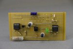
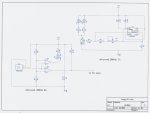
My buggy-bot kept bumping in to things when reversing, so I gave it some eyes, Infra-red ones. Fairly simple, a ICM555 cmos timer running at 38KHz, this drives an NPN transistor, which in turn drives the 2 IR Leds.

The receiver was a TSOP2438 device, this has an active LOW output, which can be confusing, and as I like all my signals the right way up?? I used an LM393 dual comparator to invert it to an HIGH. The other comparator then provides confirmation by lighting the Green Led.

I only needed to add one extra line to the program to check for an '1' on the input pin while in the reverse routine.

Here's a couple of images....
Hope it's useful
Regards
Cactusface
 

Attachments

manie

Senior Member
Cactus: Nice job there. I would also like to know "how far" the two eyes can "see" and detect an object...
 

Dippy

Moderator
Yes, well done.

Why not just invert in code? Saves hardware and hassle.

Do you get (or did you get) any problems with the IR going directly from IRLEDs to TSOP?
I see you have standoffs/pillars for the IRLEDs.
Quite a lot of IR comes out the sides of plastic cased IRLEDs and a bit of black tubing can reduce that.

Aside:
And for those that want really powerful versions note that PCB material can act as wonderful light-guides for IR and allow the IR to 'pop up' in unwanted places.
 

cactusface

Senior Member
Hi,
Thanks for taking an interest in the IR bit. Object detection distance is about 5-6cm. I am using the TSAL6400 IR LEDs, so there is perhaps a more powerful one available (any ideas?). You could reduce the 47R resistors to 33R but that might take the LEDs out of their comfort zone, by putting 110ma through each, although it's only a short pulse.

Invert the signal in code, well you might as well just check for an '0' than a '1' all my inputs are tied LOW! perhaps I'm a bit pedantic. No problems with IR over spill, tried the sleeves but has they were'nt heat shrink they kept falling off. According to the Vishay data sheet, not much IR comes out the sides, but has Dippy says I did mount them a bit higher on the board to lessen the chance of this happening.
Regards
Cactusface
 

Dippy

Moderator
"...well you might as well just check for an '0' than a '1' "
- exactly. The TSOP O/p is tied high via a resistor and triggers low.
So, a 1 means nothing and a 0 means a trigger.
No comparator or inverter needed.
No need to tie that paritcular PICAXE input low either.
I'm just trying to save your pocket money :)

Anyway, whatever you feel comfortable with, or if there are any other issues, then go with that.

It's good that you read the Data Sheet for the IRLED - many don't bother.
I tended to use the SFH485 for low/medium apps where cost was an issue.
Good performance.
I haven't looked at your circuit, but the SFH485 should be able to handle a decent current and give you a decent range (asuming physical layout is good).

But there are hundreds of IRLEDs out there and time with Data Sheets (and playing) is the only solution.

Slight tangent:
Some time ago I did a people-counting device but had a 100:1 duty cycle. 10 microS on and 1mS off. Basically it used the principle you are usng.
I was pulsng about 2 amps through the flat-ended version of this IRLED.
It did have some fancy opticals on it and got ranges of nearly 3 metres in bright sunshine.
Basically, I was happy with the performance of that LED.

Bottom Line.
Well done and you've made a useful device.
 

cactusface

Senior Member
more...IR obstacle detector.

Hi Dippy,
Thanks for you comments, I did'ent intend to dismiss them just like that! It's good that we try and save each other time and money, it's just that I had already tied all my inputs LOW, it's the way I work.. Helps me know where I am.

Only just got back into electronics after a long rest (Years), but remembered that up in the attic I had this wonderful piece of kit called a Tektronix 851 digital tester. It's not 100% working but lucky for me the Frequency meter does, so I have been able to tweek the IR circuit and now get an average 10cm detection distance.

I have heard about the SFH485 and similar are these the Sharp's ones? look like a small module with eyes!! It seems there's so much to do with a Picaxe, not sure where I go next.
Regards
Cactusface
 

Dippy

Moderator
Osram's markings can be confusing ;)

No, just standard 5mm plastic LED.
They have SFH484 and 485 and then a P on the end for flat one (which is good if you want a lens in front).

http://uk.farnell.com/osram/sfh484-2/ir-emitter-5mm-880nm/dp/1212737

and

http://uk.farnell.com/osram/sfh485p/ir-emitter-5mm-880nm/dp/1212738
(the picture is wrong - this one has a flat face).

For the IR sensor I would choose the Sharp GP1UDxxx.
Same performance basically, but with much lower power.
http://uk.rs-online.com/web/search/searchBrowseAction.html?method=searchProducts&searchTerm=gp1ud&x=28&y=19

... but all this is a bit nit-picky as you have a working device.
 

MPep

Senior Member
Congrats to your design. Thanks for sharing.
Hope your Bot doesn't get too many bruises these days :D.

May I suggest that you post this in the Finished Projects section, probably under Miscellaneous.
This way, this info will be easier to find for others, and not get lost in the multitude of posts in the general forum.

I agree with you that working in +ve logic is the more natural way to understand things. I had some sample code that just would not work for me in the simulator. Certainly seemed easy enough to understand. After re-reading the code several times, I realised that -ve logic was required. After that it made sense.

I guess the same happened when NPN transistors came into being, when PNP were more prevalent initially. Even now, looking at an older PNP circuit still doesn't quite make sense. At least initially.:D
 
Top