PWM problem

Vmax

Member
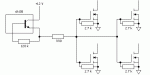
I’m a newbie with this stuff and I need help. I’m trying to use a Picaxe 28X1 to drive a PWM switch. I’m using a small 12VDC fan as test load. I made this circuit on a solderless board (attached 1).

The Picaxe drives an opto (4N35), which drives an IFR540 from a regulated +5V supply. This circuit works perfectly and fan speed varies with duty cycle. (I know there should be a back emf diode from Fan- and Bat-, but I'm only using the Fan as test load and don’t expect much back emf in the final setup).

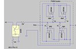
When I try to graduate from the solderless board to one where 4 MOSFETs are soldered in parallel as a separate PWM switch (attached 2) I can only get the Fan to be either OFF or fully ON. Fan speed no longer varies with duty and I can’t figure out why.

P.S. Forgive my crappy circuit diagrams. I’m also a newbie at CAD.
 

Attachments

premelec

Senior Member
Not entirely sure of what's up but in your second diagrams 10K is now 100K I think... note that power MOSFETs have high gate capacitance which affects turn on and turn off with the RC time constant - perhaps that's a problem - look at the MOSFET data sheet to get gate capacitance and see what your RC time constants are...
 

BeanieBots

Moderator
You really should fit the diode to catch back emf. Not only do you not expect much, nor does the poor old FET which will expire if it does get some!

The circuit diagram as drawn is almost impossible to follow but looks OK.
Always try to draw a diagram with power from top to bottom and signal from left to right. Keeping to that rule is just like writing from left to right with correct grammer. Much easier to understand.

The fact that you can turn the fan on and off, suggests that the power part of your circuit is OK.
When you say "either OFF or fully ON", does it do nothing until a certain PWM value is reached? If yes, what value?
Can you control the fan on/off correctly with high/low commands?
Double check your download circuit and reset connections.


added
Well spotted premelec.
The 100k (which was 10k) is unlikely to be enough to discharge the gate capacitance before the next pulse. Using an opto isolator does not give any discharge current so only the 100k can drain.
 
Last edited:

moxhamj

New Member
A capacitor may make back emf worse as it will store the charge. A 4001 diode is worth a few cents.

Picaxes can do odd things with high power near them - the chip may be resetting for instance. Put a 1 second flash on a led in a startup routine to exclude this. Then maybe try removing the pwm instruction and replacing with high/pause/low/pause in a loop. It will be slower which will make debugging easier. Make the pwm once a second - then you really can see what is going on.
 

Tom2000

Senior Member
My guess is that you're having a problem with gate capacitance.

First, drop the PWM frequency as far as you're able. Here, slower switching is better.

Next, change the gate drive circuit as I've shown in the attached sketch. That should give you a pretty hard pull to +8 volts on the gates.

If you're still not switching properly, try dropping the values of the 330 and 2.7 k resistors, maintaining the ratio between them. This should help your turn-off time. You can drop the resistances right down to the point where the 4N35's output transistor is working at about 2/3 its Ice rating.

If you still aren't switching properly, try a base resistor on your 4N35. In the sketch, I've shown a 120k resistor. You might start with 1 meg and work your way down. (If the new gate drive circuit works, don't worry about the base resistor on your opto.)

Good luck!

Tom
 

Attachments

Last edited:

BeanieBots

Moderator
Depends on the motor type.
Don't forget, if it's a fan designed for a computer, it will be well suppressed anyway.
Brushed motors need good suppression. Brushless DC fan motors usually don't.
Fit the back emf diode with either type.
 
Top