START HERE: INDEX >> http://www.picaxeforum.co.uk/entry.php?124
Items covered in this blog entry:
1-1 AMPY2001-11
Markings:
AMPY2001-11
AMPY 2001-11
DISPL3953
CB-AMP2001#6-01
I've put the pinout here but reversed it because the pinout in the datasheet is for the view from the back but you'll usually be wiring it when looking at the front.
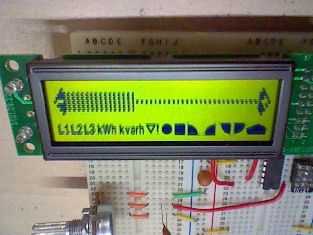
These displays are used in Enel smart meters in Italy. Their website says that the smart meter project began in 2001 which explains the product code (AMPY2001-11) and there is a "bidirectional" version of the power meter for customers who have their own "production plant", which may explain the three phase indicators. For a normal meter, only the L1 symbol will be lit.
This blog entry isn't advertising blurb - there is no documentation included for the HD44780-compatible display apart from a pinout and I couldn't find a datasheet on the internet which was a pain when I discovered that it's a 16x1 LCD with a second row of symbols! The characters themselves are also only 5x7 instead of the more usual 5x8 so take that into account if you want to use CGRAM characters on the first row or the visible cursor.

The symbols are addressed like the characters on a second row of a 16x2 LCD would be, so the addresses start at 192 (line 1 character 0 for those using that system whose name starts with an 'A'). The pixels on the first row of the 5x8 character control the individual parts. See the table below - these pixels are numbered from 1 (top left pixel) to 5 (top right pixel). The character locations for these symbols is about the same as for the 5x8 characters on a 16x2 LCD, but the 'h's are controlled by the character location following the kW/kVar that they are associated with. Also, the ∇ and ! are controlled by the same pixel.

There's no need to define CGRAM characters to use the symbols - certain letters will activate the right pixel(s) and other pixels don't matter. Examples: 'D' for first pixel, 'B' for the first and second to last pixels, 'I' for the second to last pixel only, 'J' for the two last pixels, 'd' for the last pixel only and 'E' for all three pixels.
The LEDs are controlled using transistors built-in to the module and the resistors are built in too. The anodes of the LEDs are connected to one side of the button so that means that if you want to use the LEDs then the button must be wired between power and the input pin, not ground and the input pin.
The only downsides are no backlight, no pin for a manual contrast control without modifying it (see below) and the symbols mean that you cannot change the viewing direction (which is 12:00). There is a built-in resistor for the correct contrast level at 4.5-5V but if you want to use the display at 3V and use a negative voltage generator charge pump for the contrast control, you'll need to mod it. Once modded, the LCD module can be powered by 3V if an external negative voltage generator is used. If you won't use the symbols, you can initialize the LCD for one line (instead of two) which will be beneficial if using 3xAA batteries.
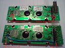
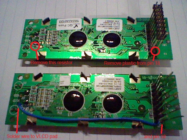
To add an external contrast control, R13 needs to be removed and a wire run from the VLCD pad to the unused pin 18 on the connector as shown in the picture below. Click the picture to view full size.
1-2 LXC1615ETR
Markings:
LXC1615ETR
PC-1601A1
This display is a standard 16x1 HD44780-compatible LCD with a single COB package so the display is addressed as two rows of 8 characters, and the 16 characters have the following addresses:
128,129,130,131,132,133,134,135, 192,193,194,195,196,197,198,199.
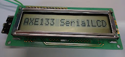
As you can see in the picture, this display is directly compatible with Rev-Ed's AXE133 and can be plugged straight in.
The contrast of this display is horrendous and only gets as good (least bad) as in the photo if viewed from below (6:00 viewing direction) and the contrast adjusted carefully. The PCB appears to have a date code of 9530 (week 30 of 1995), 12 years after the Supertwist LCD was invented, and the contrast is fine if one-line mode (1/8 duty cycle, only first 8 characters work) is selected. This suggested that the blame led with R4 being a zero-ohm resistor (1/16 duty cycle requires a five-resistor divider), though changing the zero-ohm resistor to 6.8k made little difference and contrast remained poor, so the real reason is probably the tight-fisted use of a TN panel rather than STN.
Pinout:
1-3 08580002-N08YBN00 COG LCD
Markings:
08580002-N08YBN00
Addressing is as usual for 16x2 LCDs, line 1 starts at 128 and line 2 starts at 192.
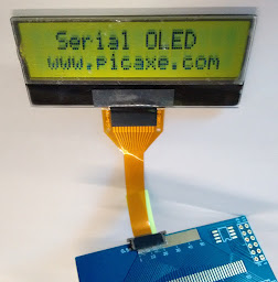
This display has good contrast and a 12:00 viewing direction (look down at it). Connection is via an FPC with 0.5mm pitch, though a 1.0mm pitch may be obtainable by cutting the FPC below the thicker tracks near the display and scratching off the insulator.
Unlike most HD44780-compatible LCDs, this display will not show a line of black squares when uninitialised - you must make all the connections before you can test it!
Vo is pin 2 and Vdd is pin 3, swapped compared to a normal HD44780-compatible LCD. This pinout is commonly found on LCDs using an NT7603 controller, a COG (Chip on Glass) HD44780-compatible controller.
Pinout: (Pin 1 is on the left when viewing the LCD)
3-1 LCD with pins
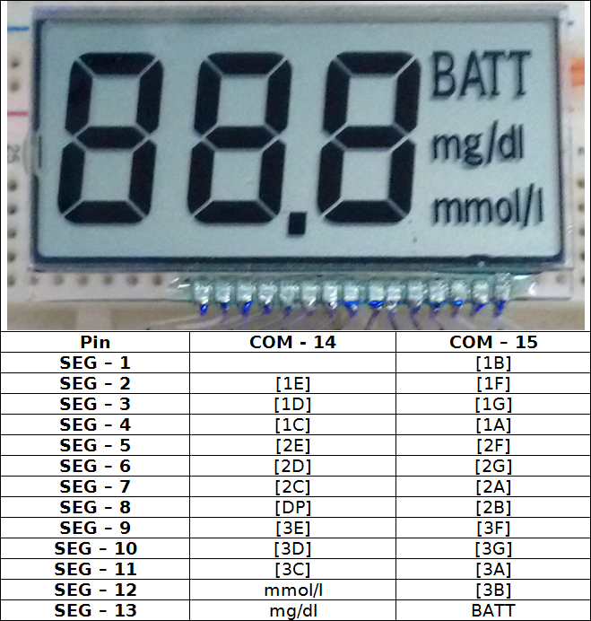
This display has no markings and has 15 pins on an unusual pitch. You can solder LED offcuts onto them to connect this display to breadboard. Application of this display would have been a glucose meter. This display operates with a 1/2 duty cycle as it has two commons, and it has 13 segments. The viewing direction (or bias angle) of the display is 6:00, meaning it's best viewed from below.
Pinout: (pins numbered with 1 at the left, 7-segment digits numbered with 1 at the left)
I would expect this display to be difficult to drive directly with PICAXE, though it might be possible.
Items covered in this blog entry:
- Varitronix 16x1 + symbols COB LCD (AMPY 2001-11)
- '90s 16x1 COB LCD (LXC1615ETR)
- 16x2 COG LCD (08580002-N08YBN00)
- LCD with pins
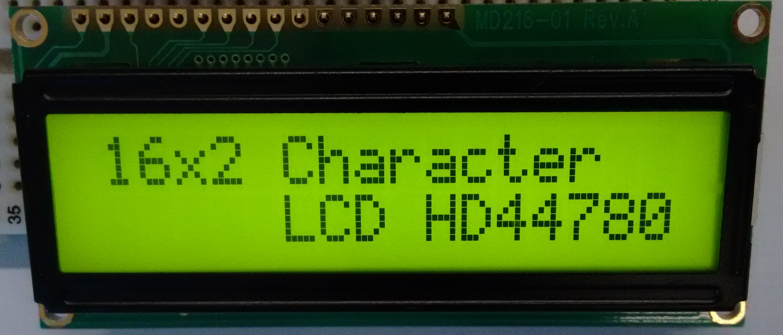
- 16x2 COB character LCD MD216-01 (scroll down to comments)
- NEW! 128x64 graphic LCD WAYTON M.I.T PC-1206E2 (scroll down to comments)
- OLED (OS96016PP08MB2B10) (scroll down to comments)
1-1 AMPY2001-11
Markings:
AMPY2001-11
AMPY 2001-11
DISPL3953
CB-AMP2001#6-01
I've put the pinout here but reversed it because the pinout in the datasheet is for the view from the back but you'll usually be wiring it when looking at the front.
These displays are used in Enel smart meters in Italy. Their website says that the smart meter project began in 2001 which explains the product code (AMPY2001-11) and there is a "bidirectional" version of the power meter for customers who have their own "production plant", which may explain the three phase indicators. For a normal meter, only the L1 symbol will be lit.
This blog entry isn't advertising blurb - there is no documentation included for the HD44780-compatible display apart from a pinout and I couldn't find a datasheet on the internet which was a pain when I discovered that it's a 16x1 LCD with a second row of symbols! The characters themselves are also only 5x7 instead of the more usual 5x8 so take that into account if you want to use CGRAM characters on the first row or the visible cursor.
The symbols are addressed like the characters on a second row of a 16x2 LCD would be, so the addresses start at 192 (line 1 character 0 for those using that system whose name starts with an 'A'). The pixels on the first row of the 5x8 character control the individual parts. See the table below - these pixels are numbered from 1 (top left pixel) to 5 (top right pixel). The character locations for these symbols is about the same as for the 5x8 characters on a 16x2 LCD, but the 'h's are controlled by the character location following the kW/kVar that they are associated with. Also, the ∇ and ! are controlled by the same pixel.
There's no need to define CGRAM characters to use the symbols - certain letters will activate the right pixel(s) and other pixels don't matter. Examples: 'D' for first pixel, 'B' for the first and second to last pixels, 'I' for the second to last pixel only, 'J' for the two last pixels, 'd' for the last pixel only and 'E' for all three pixels.
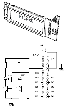
The LEDs are controlled using transistors built-in to the module and the resistors are built in too. The anodes of the LEDs are connected to one side of the button so that means that if you want to use the LEDs then the button must be wired between power and the input pin, not ground and the input pin.
The only downsides are no backlight, no pin for a manual contrast control without modifying it (see below) and the symbols mean that you cannot change the viewing direction (which is 12:00). There is a built-in resistor for the correct contrast level at 4.5-5V but if you want to use the display at 3V and use a negative voltage generator charge pump for the contrast control, you'll need to mod it. Once modded, the LCD module can be powered by 3V if an external negative voltage generator is used. If you won't use the symbols, you can initialize the LCD for one line (instead of two) which will be beneficial if using 3xAA batteries.
To add an external contrast control, R13 needs to be removed and a wire run from the VLCD pad to the unused pin 18 on the connector as shown in the picture below. Click the picture to view full size.
1-2 LXC1615ETR
Markings:
LXC1615ETR
PC-1601A1

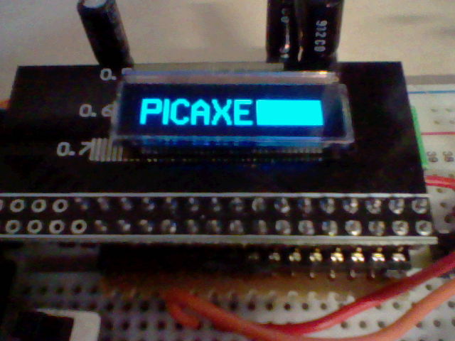
This display is a standard 16x1 HD44780-compatible LCD with a single COB package so the display is addressed as two rows of 8 characters, and the 16 characters have the following addresses:
128,129,130,131,132,133,134,135, 192,193,194,195,196,197,198,199.
As you can see in the picture, this display is directly compatible with Rev-Ed's AXE133 and can be plugged straight in.
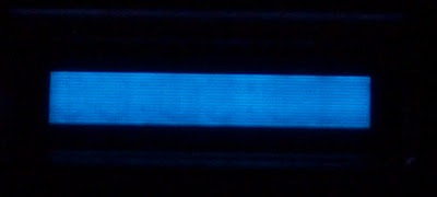
The contrast of this display is horrendous and only gets as good (least bad) as in the photo if viewed from below (6:00 viewing direction) and the contrast adjusted carefully. The PCB appears to have a date code of 9530 (week 30 of 1995), 12 years after the Supertwist LCD was invented, and the contrast is fine if one-line mode (1/8 duty cycle, only first 8 characters work) is selected. This suggested that the blame led with R4 being a zero-ohm resistor (1/16 duty cycle requires a five-resistor divider), though changing the zero-ohm resistor to 6.8k made little difference and contrast remained poor, so the real reason is probably the tight-fisted use of a TN panel rather than STN.
Pinout:
| Pin | Name |
| 1 | Vss (GND) |
| 2 | Vdd (+5V) |
| 3 | Vo (Contrast) |
| 4 | RS |
| 5 | R/W |
| 6 | E |
| 7 | DB0 |
| 8 | DB1 |
| 9 | DB2 |
| 10 | DB3 |
| 11 | DB4 |
| 12 | DB5 |
| 13 | DB6 |
| 14 | DB7 |
1-3 08580002-N08YBN00 COG LCD
Markings:
08580002-N08YBN00

Addressing is as usual for 16x2 LCDs, line 1 starts at 128 and line 2 starts at 192.
This display has good contrast and a 12:00 viewing direction (look down at it). Connection is via an FPC with 0.5mm pitch, though a 1.0mm pitch may be obtainable by cutting the FPC below the thicker tracks near the display and scratching off the insulator.
Unlike most HD44780-compatible LCDs, this display will not show a line of black squares when uninitialised - you must make all the connections before you can test it!
Vo is pin 2 and Vdd is pin 3, swapped compared to a normal HD44780-compatible LCD. This pinout is commonly found on LCDs using an NT7603 controller, a COG (Chip on Glass) HD44780-compatible controller.
Pinout: (Pin 1 is on the left when viewing the LCD)
| Pin | Name |
| 1 | Vss (GND) |
| 2 | Vo (Contrast) |
| 3 | Vdd (+5V) |
| 4 | RS |
| 5 | R/W |
| 6 | E |
| 7 | DB0 |
| 8 | DB1 |
| 9 | DB2 |
| 10 | DB3 |
| 11 | DB4 |
| 12 | DB5 |
| 13 | DB6 |
| 14 | DB7 |
3-1 LCD with pins
This display has no markings and has 15 pins on an unusual pitch. You can solder LED offcuts onto them to connect this display to breadboard. Application of this display would have been a glucose meter. This display operates with a 1/2 duty cycle as it has two commons, and it has 13 segments. The viewing direction (or bias angle) of the display is 6:00, meaning it's best viewed from below.
Pinout: (pins numbered with 1 at the left, 7-segment digits numbered with 1 at the left)
I would expect this display to be difficult to drive directly with PICAXE, though it might be possible.