Picaxe-based Satellite: PongSat-18X

kranenborg

Senior Member
Hello,

In this thread my son Joost and I want to introduce our near-space PongSat-18x project. We have several questions and hope that forum members are willing to join in design discussions; we'll keep you informed about our progress. The idea is that this miniature 18X-based satellite will fly within a month towards near-space.

A pongsat (http://www.jpaerospace.com/pongsat/index.htm) is an experiment that fits inside a pingpong ball and will be flown to the near-space area (about 30 kms high if we are lucky) free of charge by company called JPAerospace. There have been some Basic Stamp and picaxe-based pongsats before. They have recorded the temperature at the beginning of the trip in the air; at some point the temperature gets so low that an ordinary battery freezes and thus the experiment finishes, long before the highest altitude has been reached.

We have registered for the planned flight of 2 May, and we decided to aim a little bit higher. Our goals are:
- To develop a picaxe-based pongsat that functions properly through the *whole* flight (this implies that very low temperatures (-70 Degr. C or less) may be encountered),
- To do a large number of measurements (not just temperature) very regularly and thus learn about the atmosphere.
- To test a number of sensors for their appliccability
- To run the project like a real space project, i.e. build and test prototypes thoroughly and under "harsh conditions", thorough preparation etc.

Like in a real space projects there is the risk of total failure in several stages, but that's what we happily take for given ;o) The road towards it is as exciting as the final flight and data retrieval.

Here are some impressions of our designs:


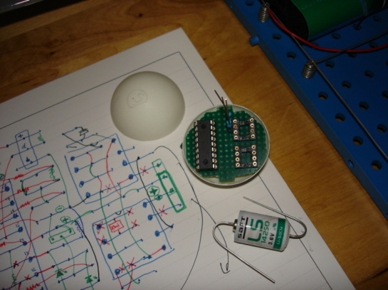
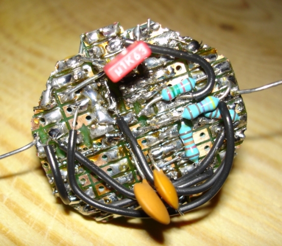
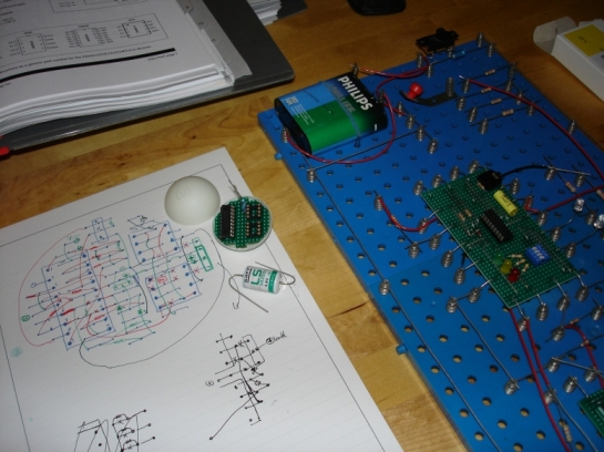
picture 1: Pongsat, print layout scetch and special battery that fits within the PongSat


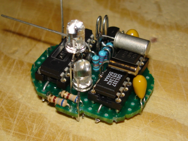
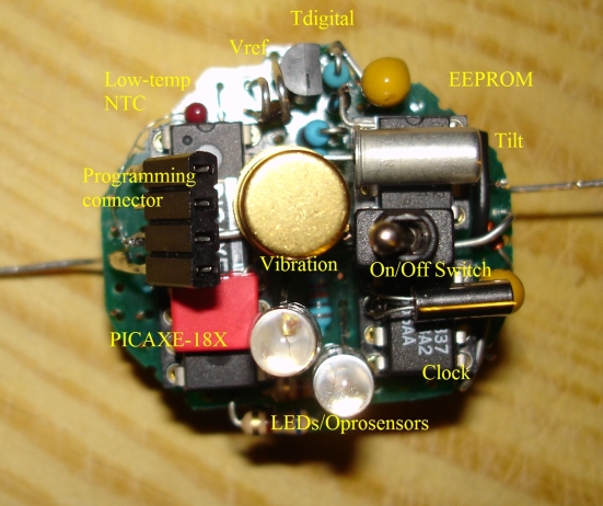
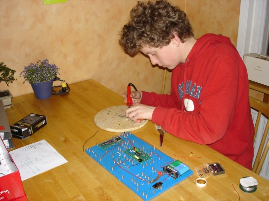
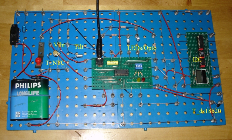
picture 2: Project elements: prototype testing model (based on Philips EE system, http://www.kranenborg.org/ee/ , with identical circuit)

Central to the idea is a PICAXE-18X based flight computer that is designed for very harsh conditions: low voltage due to very low temperatures. The computer is powered by a special Lithium polymer battery that has a guaranteed functionality down to -65 degs C !


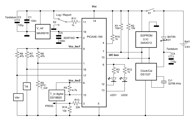
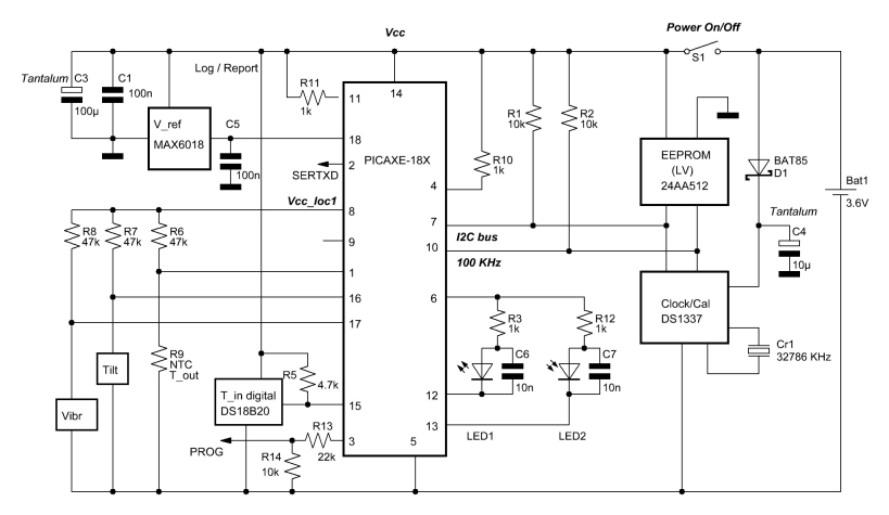
picture 3: Circuit diagram

The circuit reveals that the flight computer has similarities with Rev-Eds datalogger kit, however we use different components that can operate under very low voltages (1.8V); the battery can operate at very low temperatures but the voltage drop at low temperatures is considerable as well and may be below the "standard" 2.7V limit.

The computer has 7 sensors (whereof 4 analog), all served by the 18X (how? thanks to hippy's pokings, see the following link: http://www.picaxeforum.co.uk/showthread.php?t=9086 ):

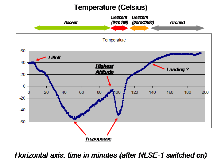
- Internal temperature (digital, DS18B20)
- External temperature (analog, thermistor outside)
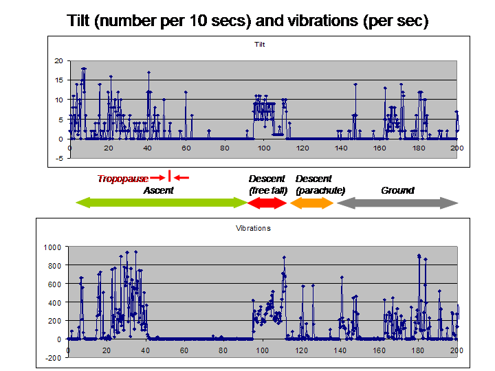
- Tilt sensor (internal, requires the pongsat to be in fixed position), to indirectly measure wind effect, obtained via Rev-Ed
- Vibration sensor (another way of indirectly measuring wind speed, also via Rev-Ed)
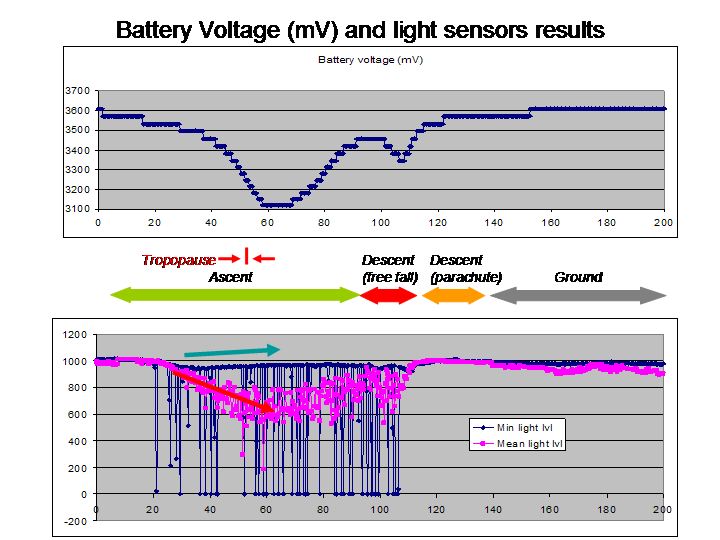
- Two light sensors (using LEDs with inverse charging/discharging) to measure darkening effect at high altitudes (inspired by wilf_nv, see http://www.picaxeforum.co.uk/showthread.php?t=5945 ). The LED will also be used in a normal way to indicate proper functioning at start-up
- Battery voltage monitoring for measuring voltage drop at low temperatures (Using MAX6018 voltage reference device)

All information will be stored in the special low-voltage 24AA512 EEPROM with an interval of approx. 20 secs.

As you can see development is at full speed now (I'll do mostly hardware, Joost has begun programming, we do the prototype model together), we'll come back soon with a lot of issues that we would like to get help with. Meanwhile we are open for any discussions on the design!

Jurjen & Joost Kranenborg
 
Last edited:

hippy

Technical Support
Staff member
Whoo, that sounds like an amazing adventure to be involved with and good luck. I'm sure it'll take pride of place on the mantlepiece once it's been into space.

Probably late in the day but a few thoughts ...

Do you need the RTC ? Use on-chip Timer 1 with the 32kHz as a Low Poer Osc and you can probably get an as equally accurate timebase / timer. That saves space and reduces current drain.

Can you sandwich the PICXE between the R's ( on top and underneath ) ? That may give a little extra heating which keeps the PICAXE going for a little longer.

What about a low-R which does work as a heater under the PICAXE ? You could drive that via PWM to adjust the temperature. Nothing to lose by draining the battery quicker if it eeks out a few extra seconds of PICAXE life.

A compact design with components under/over each other, vertical R's may give a smaller core, small enough to get two batteries in there if lucky. SMT might help, an SMT PICAXE could perhaps be easier to keep warm ?

Maybe a dead-bug wiring scheme would be even more compact but more fragile.
 

kranenborg

Senior Member
Stan: Somehere in California close to the Nevada desert these PongSats are flown together with other bigger and more advanced instruments into the air and back on earth again, using balloon-lifted platforms. A GPS system and transmitter is present (not a pongsat ;o) in order to locate the platform when they are back on earth again. Afterwards the pongsats are returned to their owners via mail

Hippy: Your reactions are highly appreciated, here is the response to your remarks:

Do you need the RTC ? Use on-chip Timer 1 with the 32kHz as a Low Poer Osc and you can probably get an as equally accurate timebase / timer. That saves space and reduces current drain.

I have considered this option (as I currently need to place the MAX6018 voltage reference somewhere hanging in the air), but Timer 1 use requires pins 12 and 13 for the 32786 Hz crystal connection and these are exactly the extra ADC pins available when poking port B ... . I prioritized the option to use the two LEDS as optosensors, but I was close to choosing the timer use and thus saving circuit board space.

Can you sandwich the PICXE between the R's ( on top and underneath ) ? That may give a little extra heating which keeps the PICAXE going for a little longer.

What about a low-R which does work as a heater under the PICAXE ? You could drive that via PWM to adjust the temperature. Nothing to lose by draining the battery quicker if it eeks out a few extra seconds of PICAXE life.

A compact design with components under/over each other, vertical R's may give a smaller core, small enough to get two batteries in there if lucky. SMT might help, an SMT PICAXE could perhaps be easier to keep warm ?

Maybe a dead-bug wiring scheme would be even more compact but more fragile.


We have thought above the above options in a similar way, primarily opting for battery heating (max 50 mA can be drawn from the types used, but this may be less at lower temperatures, thus a control strategy is needed) using mosfet-switched resistors and using special IC sockets with pins sideways and connecting these together around the battery, thus maximizing thermal radiation heating (most of the air is gone, so radiation may remain as the most inportant thermal transport process). However, this approach makes it very difficult to add the various extra components (Still a lot of them, it is a pity that only port B supports programmable pullups, whilst I need them at the "official" inputs at port A) and I am very limited in the soldering tool sand experiences. The idea of use of SOIC parts is an interesting option however I did not take into account.

For a next fligth it may be interesting to develop a special PongSat with "Climate Control" using hippys and my arguments above, and see whether this is technically feasible? Maybe developed purely via the Forum? This would require a thorough understanding of battery physics.

In the meantime we have made progress; the prototype board is finished as shown below (circuit identical to pongsat) , and we are currently proceeding well with testing the sensors.


Picture 4: Joost soldering long wire legs to the sensors for connecting them to the prototype board


Picture 5: The finished (and apparently functioning) prototype board, with sensor locations indicated (only the voltage reference device is lacking).

The sensors generally appear to work as expected, but the tilt sensor is att odds, we'll come back with a reaction on that one, as it behaves somewhat unexpectedly. Almost bedtime now.

Some other issues that maybe someone can help us with:

1) All semiconductor devices are rated down to -40 deg. C. What may we expect to happen when their temperature gets even lower? Does it help to lower the clock frequency of the 18X in that case? ( we alsready use a 100kHz i2c speed)

2) During the project we have come to realize that maybe the biggest threat to the succesful conclusion of this project may be the mail transport toward JPAerospace and back; this one may look like a true bomb at customs. Is there anyone who could advice us on reducing this transport risk? Electronic cicruitry does attrack attention; we have had several posts with electronic greeting cards send from the Netherlands to Sweden (i.e. EU-internal) opened, in one case the card did not function.


As you can see this project focuses much on technology design; we are very keen on thinking more on advanced sensing and control for future projects, in which the 18x will probably remain the key player.

Next step: understanding the tilt sensor behaviour (this is the device: http://194.201.138.187/epages/Store.storefront/?ObjectPath=/Shops/Store.TechSupplies/Products/SEN010 ) and testign the two LEDs as optosensors. I will also start soldering the PongSat print, as it now seems that the circuit design is OK.

Best regards,
Jurjen
 
Last edited:

MORA99

Senior Member
Cool project :)

The DS18B20 is only rated to measure down to -55, have you tested it in lower temperatures ? (dry ice maybe)

What about isolation, dont know if it does any difference at those temperatures, with the low amount you can fit in there.
 

womai

Senior Member
Why not use surface mount components (as far as available)? SOIC packages aren't too hard to solder even for a layman. Surface mount will need less board space and MUCH less volume (especially compared to socketed DIP), and I'd expect to to be more rugged, too. Probably too late right now, but if you do it again I'd volunteer to do the layout and PCB manufacturing (double-sided, which will save even more space) for free. Since surface mount will also result in a much lower height, you could even think of fitting two boards on top of each other, for even more space for additional circuitry.

Wolfgang
 

Mycroft2152

Senior Member
Great project! Good luck on the flight!

As a retired model rocketeer form the '70s, I'm amazed how far things have come along!

If anyone hasn't checked out the PONGSAT site, do so.

I do have a fcouple of questions:

How long is the flight?

How do you start and stop the data collection?

I can't see the PONGSAT guys flipping switches on 500 ping pong balls.

Myc

Myc
 

Mycroft2152

Senior Member
Slurp,

2.5 hours sounds about right.

according to the website, they rmust receive the PONGSAT 6 days before launch.
There may be some info in the PONGSAT project package about manually triggering projects.

Note to Jurgen:

You may want to check out the picaxe model rocket data collection projects for some ideas.

Also, filling the PONGSAT with injectable foam insulation wil help maintain the temperature, though a real pita to remove. I used this trick during a model rocket egg lofting event to protet the egg from cracking. Managed to get 3rd place in the nationals.

Myc
 

MFB

Senior Member
Magnetic tilt sensor

You mention that your having problems with the tilt sensor. Have you considered using the vertical component of the Worlds magnetic field to detect tilt? Honeywell and Philips produce a range of magnetic sensors that have the required sensitivity. Although they are only able to provide a raw bridge output of a few mV maximum, an instrumentation amplifier (single SOIC package) with a gain of about 500 will provide reasonable ADC resolution. This technique has been used for some years for detecting apogee on model rockets.
 

kranenborg

Senior Member
Due to what appears to be a server problem at my internet provider it seems that the links towards the pictures point to the blue sky instead of the pictures meant. I will upload the pictures again this evening, and then respond to the various reactions.

Sensor testing is now almost ready (and we found a solution to the tilt sensor problem by writing a small subroutine for interpreting the data)

Jurjen
 

kranenborg

Senior Member
The whole test circuit is operational now (both hardware and software, including data storage and retrieval) so it's time to begin soldering the pongsat circuit. In the meantime we'll keep the identical test circuit operational in order to have more advanced output options (a StampPlot interface) in the program and do some other final adjustments to the software (in particular sensor settings for daylight conditions). It has already been a very enjoyable adventure, as we have learnt some new things by dealing with the sensors.

The two sensors that gave us some extra work were the tilt sensor and the use of LEDs as optosensors using the 18X output pins reconfigured as inputs.

Firstly, the tilt sensor when in the on state appears somewhat surprisingly to act as a vibration sensor, therefore it does not really register tilt. This problem was easily solved by dividing the measurement interval in short ones, register the number of changes per short interval (using the COUNT command) and then define a change in tilt as a difference between one state (0 transistions) and the other (one or more transitions) when comparing the current interval with the previous one.

The opto-LEDS testing happened in two stages. First Output 6 and 7 had to be redefined as ADC inputs. This is done by first enabling them as inputs, and then (after a waiting period to allow the incident light to discharge the reverse-charged LED) to configure and enable the ADC module and finally performing the conversion. Since a READADC10 command must be simulated by a few PEEKs and POKEs this requires considerably more time to execute. This fact, and the relatively low impedance of the input when the ADC module is enabled, causes the LEDs to be discharged completely before the read is done. As a working remedy I added a 10nF capacitor in parallel with the LEDs (This is not needed when using standard ADC inputs with READADC10). I will publish the codes for enabling the outputs as ADC inputs in the code snippets section (maybe hippy is willing to refer to it in his SFR usage thread).

Some reactions to previous posts:

@Mora99: No, we have not tested the DS18B20 at very low temperatures. What we foresee as a more serious problem is the voltage drop if the battery due to low temperature; the minimum operating voltage is 3V. This is one of the reasons why we want to include the voltage reference in order to continuously monitor the battery voltage. We have thougth of isolation experiments in the future.

@womai: Thanks for the print offer, but maybe we can develop the next version as a joint Picaxe Forum project, using your capabilities to create a very compact print layout and thus an even more powerful version. Maybe we should regard our current project as a feasibility study, and if it appears succesful we can aim really high and define on the forum a much more advanced version, with a work division between several members (we for example could do prototype testing with our philips ee system) and proper planning.

@mycroft2152 and @slurp: The flight is about 2.5 - 3 hours, plus some "dead time" after the landing. Indeed our pongsat has to be switched on and off, but the places available for these special pongsats is limited. The foam insulation sounds interesting, i haven't made up my mind on this yet.

@MFB: As we reported on previously, the problem with the (very cheap) tilt sensor has been solved by a few codelines extra and does give satisfactory results now. Note that we included both tilt and vibration sensors as wind effect sensors, primarily because we suspect that the vibration sensor may be too sensitive ...

Best regards,
Jurjen
 
Last edited:

Mycroft2152

Senior Member
Have you looked at your energy budget on the battery? If there is enough capacity to run a small heat source ( LED or bulb). Along with the insulation you may be able to maintain the internal temperature of the battery.

Of course if you were NASA, you would have a small radioactive pellet to do the job as is used on the Mars Rovers.
 
Last edited:
Interesting Project!


The clock frequency, as you suggested may be a key part of this... to keep it alive for a bit longer.

Can I suggest you reduce it with a external resonator, to something like 1 Mhz, and speed up the I2C in the software to 400khz - so It will still be doing 100khz.

Don't forget, If your 24AA512 fails, no data can be recorded.
 
Last edited:

kranenborg

Senior Member
Considerable progress has been made, and we learned a lot about the picaxes internal operation due to a very annoying and persistent failure of operation, that we were finaly able to resolve ourselves ... More on that below.

The software runs flawlessly on the hardware propotype now, and the identical PongSat hardware is getting in a final stage too, as shown in this picture:


The PICAXE-18X is on the left, the clock with the crystal on top on the foreground, and right back is the memory chip with the tilt sensor hanging over it. Back in the transistor casing is the DS18B20 temperature sensor, and barely visible on the left side of it is the tiny MAX6018 voltage reference chip (mounted to the wires, which was a horrible job to do). The leds act as light emitters as well as sensors. The vibration sensor still has to be added

As always there remain some tough problems to be resolved at the end, and we dealt with the following:

- It appears that the PICAXE firmware for the READADC instruction does not initialize the ADCON1 register (it probably assumes a zero value at startup). Since this register is changed in our software that reconfigures Output 6 and Output 7 as ADC inputs (its MSB bit is set for proper shifting of a 10-bit conversion result in a 16-bit register), it finally appeared to cripple the READADC operations later on (for battery voltage reading). It took quite a few hours to pinpoint and solve it (but with great satisfaction because we did it ourselves), and I added this in the code snippets section (where I posted the Port B Output reconfiguration for additional ADC inputs) as well. Maybe a suggestion to Technical to add the explicit initialization in firmware?

Soldering gets complicated at the end as well, but most is done now. Due to lack of space the switch for log/readout is not implemented, we will log only, and subsequently after the trip we can download the results by reprogramming (as a download interface will be implemented)

Regards, Jurjen & Joost
 
Last edited:

kranenborg

Senior Member
Like in a real space project the PongSat-18X (Code name NLSE-1) has been sent away, unreachable, ... by mail to the USA (last Monday). The picture below shows almost the latest stage (on one of the LEDs a black straw was mounted in order to catch background light only). Just before packaging the circuit was tested fully OK, and the clock is already running now. Lets see how US Customs reacts to this one. Together with this one four other PongSats are packaged containing some plant seeds and marshmallows, in order to do some biological and solid mechanics experiments ...


Due to the large number of wires at the backplane (as well as some extra components) the circuitry did not fit competely in the pingpong ball as I had wished. As a consequence I decided to leave it largely open at the top. Next time a professionally designed circuit board by Womai and using surface-mount components should cure that problem.

The picture below shows the positioning of the sensors:


The back plane quickly became a mess and looks as follows (although the circuit worked flawlessly right away):


I have tried to increase the chance of getting the flight data unspoiled by asking JPA to cut away one of the wires on the side of the ball prior to shipping back, effectively removing the battery from the circuit.

The final circuit is shown here:


The documented code for the PongSat is included as an attachment. Note that in the program body a provision is made for a temporary low-power sleep/wake-up mode when the battery voltage gets dangerously low at very low temperatures (2.3V shutdown and temporary sleep, wakeup at 2.6V).

If this trip is going to be successful and we get the thing back in good shape, it might fly for a second time; I already got several software improvement ideas (for example the light sensors could be calibrated authomatically at start-up (i.e. sensitivity), and the NTC data could be converted by the Picaxe directly to temperature using table look-up). There is plenty of space for improvement, as less than half of the code space is currently in use. Having done this project I am still amazed by the flexibility and power of the 18X.

I am now eagerly awaiting a signal from JPAerospace Ground Control, most likely in the beginning of next week.

Regards,
Jurjen
 

Attachments

Last edited:

kranenborg

Senior Member
The flight that should have been performed at 2 May has been delayed by about a week, so hopefully some reports within 10 days ...

/Jurjen
 

kranenborg

Senior Member
The mission was delayed again, but is planned still for the near future. I hope this will be in a few weeks

/Jurjen
 

MFB

Senior Member
Interim 28X2

What a great contribution. Do you know if anyone has done similar work to obtain more than four ADC inputs from a 28X1? I really need the extra analog channels and veriables promised on the 28X2 but can't now remember which summer this product was going to be introduced.
 

kranenborg

Senior Member
JPAerospace is planning for the release right now, and seems to have resolved some technical issues that blocked the flight to be performed earlier. Still some weeks, probably

/Jurjen
 

profmason

Member
pongsats

Hi folks,

We launched a half dozen picaxe based "pong sats" just over a year ago. There is a rudimentary link at:
http://profmason.com/?p=275
Some day I will get the students to post the rest of the documentation.

The one piece of advice I wish I had known....... It gets VERY cold at altitude. We used small lithium batteries producing around 4 volts. As they cooled down the voltage dropped which meant that the processors shut down. You will want to either
1. Insulate your batteries.
2. Heat your batteries.

Be sure to test in the freezer.

good luck!
mmason
 

kranenborg

Senior Member
I became aware of the low temperatures (and other harsh conditions) through Paul L. Verhage's on-line book (in particular Chapter 8, "Near-Space Experiments): http://www.parallax.com/tabid/567/Default.aspx. This caused me to look for special batteries, and I was lucky to found the appropriate one in 1/2 AA size, which is the one that is used in our PongSat-18X. Paul's book is definitely worth reading.

We appear to be close to launch right now, see http://www.jpaerospace.com/blog/

/Jurjen
 

kranenborg

Senior Member
Happy to say that we are still fully in the race (and the launch will be soon now), as I got direct confirmation from JPA Ground Control this morning that all of our PongSats arrived happily and in working condition! This is a great relief because it is the first confirmation that our stuff passed international borders unspoiled.

There is proof too! John Powell put some nice pictures for the Away 35 on their site (http://www.jpaerospace.com/blog/) and the first photo shows that our NLSE-1 got a VIP seat!

This is getting up to speed now ..., stay tuned ;o)

Regards,
Jurjen
 

jobapi

New Member
Successfull data retrieval !!!

Hi
I am Jurjen's son Joost.
When I saw the big cardboard box on the kitchen table I knew it was from JPAerospace containing our pongsats.
The pongsats were still intact and we managed to get all data out of the chip. It funcioned throughout the whole journey! Almost all sensors gave us a lot of information (for example the temperature and movement sensors; The minimum temperature was -56 degrees C and the inversion layer was clearly visible in the graph). We are now analysing the data in more detail and trying to make some more conclusions. We already know that the battery power didn't even get close to the minimum voltage level required. We will soon add some pictures and photos on the forum.

---jobapi--- ;)
 

hippy

Technical Support
Staff member
@ Jurjen and Joost : Well done and I'm glad all your hard work has been rewarded. You can be justly proud of what you've accomplished. Great teamwork too.

It's said, "the sky's the limit", so what's next ?
 

kranenborg

Senior Member
Hello,

At a first glance the mission appears to have been extraordinary successful. The total height reached has been 32 kms (105,000 feet), the minimum temperature minus 56 degrees C (which could have been much lower actually), and the NLSE-1 has been registering flawlessly with intervals of approx. 20 secs (including several hours after landing, after it went into sleep mode). The special battery (rated to -60 degr C) has performed excellently, as well all other techology onboard.

Here follow two first graphs that include an interpretation of a part of the data as we know it currently (adjustments definately needed and will follow later). I particular the combination of temperature and tilt&vibration sensor readings appear very informative (to my surprise actually, because I thought that the vibration sensor would be way too sensitive)


The temperature profile clearly reproduces the structure of the troposphere (the lowest layer where we live in, with decreasing temperature with heigth, which may cause strong winds, as suggested by the figure below) and subsequently the stratosphere where the temperature increases with height causing a very stable layer, (i.e. a stable density stratification without any wind). Very marked from the data is their common boundary, the tropopause (we must have crossed the ozone layer as well ...). The absence of wind in the stratosphere is strongly suggested by the tilt/vibration readings after the tropopause is passed (since as long as the balloon is attached the tilt/vibration sensors are thought to register the effect of wind disturbing the vehicle):


You will notice that after passing the tropopause (according to JPAerospace with an average climb rate of 260 meters/min.) it gets all very calm, peaceful and silent ... up to 32 kms where the balloon bursts and the vehicle gets in a free fall. The moment of the balloon exploding is captured very well too in both graphs (and of course no wind effect registered here). After a while the parachute of the vehicle opened. From JPAerospace I got the information that fragments of the exploded balloon quite hindered the unfolding of the parachute, causing the vehicle to hit the ground much harder than expected and destroying several cameras that were mounted on booms (as well as crippling the vehicle itself). The NLSE-1 though - mounted tightly on foam boards - survived and continued operating. JPAerospace have done a fantastic job anyway, the box we got by mail last week had a lot of info, videos, and even diplomas!

The high, unrealistic temperatures registered after return (approximating almost 60 degrees C, see the first figure) are probably caused by direct exposure of the DS18B20 sensor to the sun. Furthermore the tilt/vibration sensors suggest that strong surface winds were present.

More on the battery behaviour, optical sensors data, further analysis of the temperature dependency of the clock, reconstruction of climbing and fall speeds, the other pongsats with seeds and marshmellows etc. etc later on, it seems we have still a journey regarding data adjustments and dataprocessing in front of us ... . We will make the dataset available as well

Regards,
Jurjen & Joost
 
Last edited:

kranenborg

Senior Member
Here follows some more information on the battery behaviour as well as the optical sensors (reverse-charged LEDs):


The first picture shows the effect of the low temperature environment on the battery voltage. Although the battery voltage drops somewhat (to 3.1V), it appears that the low temperature does not persist long enough to get the voltage level really down the level that the device would have goen in sleep mode to further reduce power consumption (2.3V). After the trip the battery recovers completely. It seems that this particular one (Saft LS 14250) will be the chosen one for future experiments (also because of its relatively small (1/2 AA) size)

The second picture shows the effect of light on the two optosensors. The pink graph shows the results for the LED that picks up light from a broad field, whereas the blue graph shows the one with a straw mounted, such to avoid direct sunlight or reflections entering (the dips show that it happened though) and to register the darkening of the background sky only. A lower value implies that more light has been registered (discharging the LED capacitance). The blue trend arrow (as well as the different orientation of both arrows) give a suggestion of the registration of the darkening effect (given the fact that semiconductors get more efficient at low temperatures the difference in trends is even more markedly). The effect seems to set in somewhat early though, but the suggestion is clearly there. In the current implementation the exposure time was fixed (see the code attachment earlier in this thread), but this may be calibrated in a more intelligent way.

Finally, the only sensor that has not functioned well is the external NTC temperature sensor. It has probably become too hot during soldering and would need to be replaced.

All in all it seems to have functioned remarkably well, and given the richness of the current dataset and the potential for software improvement (particularly concerning the optosensors, there is still much codespace left to do autocalibration during the flight in order to have the trends development much clearer) I am considering the option to let it fly again and see whether the analysis done so far holds. I think the current flight has shown that the technology mix used is very appropriate for this type of experiment. (would be great to get someting like this even in their rocket experiment!)

Still some analysis to be done, but like hippy said the question is also: What's next? I'll present some ideas later, but maybe others are inspired as well?
 

atharvai

Senior Member
Great

hey I know i'm little late on this thread but great project and great results. its good to know PICAXE isn't just for hobbyist or enthusiasts. Its capable of some serious stuff!
 

kranenborg

Senior Member
Thanks Atharvai. In particular the perfomance/size ratio of the 18X is remarkable, allowing such a quite complicated experiment.

The charm of a space experiment is of course that some things appear to be wrong later on, without doing too much harm. In this case it is the optosensor with the black straw mounted. I suggested that it is ithe darkening of the sky that is registered, but I do actually think that something else is recorded, namely the effect of heating of the black straw. Since the air becomes rapidly thinner it is rmainly radiation that determines the final temperature, and for a black body like the straw exposed to the sun one would expect a considerable temperature increase. As a consequence the optosensor (LED) would get relatively warm too and get less sensitive, and I think that it is exactly this that actually got registered in the blue graph. This can easily be counteracted by winding a piece of aluminum foil around the straw the next time. At least a proper motivation to let it fly once more, if we are allowed.

Considering ideas for new projects, there are several options that might be of interest:

- Trying to create a relatively warm atmosphere inside the ball though a controlled stronger loading of the battery for a short time
- Registering not only temperature but also humidity, pressure and maybe even ozone?
- Is there charge somewhere upper in the atmosphere (checked by registering the charge accumulation on an aluminum-wrapped pongsat)
- Electronically registering the effect of cosmic rays? Sounds very interesting but I have actually no idea how to sense them electronically ...

Of course there is the challenge too of further adding compnents by using smaller (SMD) components and double-layered specially made circuit print boards. With the NLSE-1 I have admittedly cheated a bit because the whole circut appeared not to fit inside the ball. This needs to be improved!

If anyone has even more challenging ideas I'd rather like to hear about them! The NLSE-1 experiment has shown that from a technical perspective the components used are appropiate for this type of endeavour, and I hope that others with similar plans may find this useful information.

As the next experiment I am considering the battery heating proposal, using an 08M and a 25AA512 SPI eeprom. We are also eager to join any cooperation project as well, if others show up with interesting ideas.

Regards, Jurjen
 

atharvai

Senior Member
Hi,
i was wondering tho, the change in temperature must have somehow affected the ICs. At -50, -60C there must be some deviation in say the operation of clock so the accuracy of frequency must have been affected?

i wonder if these electronic components work the same at those extreme temperatures.

just a thought

i'll post any idea i have
 

MFB

Senior Member
Temp effects

Great work and very interesting!

I would think that the low temperature would effect the photodetector reading. Its probably worth mounting the sensors and conditioning circuitry in a domestic freezer to check the level of drift with temeperature.
 

vk6kci

New Member
Hi Jurjen,

What a fantastic effort.

You mentioned that some of the sensors may have elevated temperatures because exposure to sunlight.

Can you take advantage of any absorpsion by painting the external of the Pongsat with a flat black paint. I guess any elevation of temperature would be beneficial.

Regards
Maarten
 

atharvai

Senior Member
Hi Jurjen,

What a fantastic effort.

You mentioned that some of the sensors may have elevated temperatures because exposure to sunlight.

Can you take advantage of any absorpsion by painting the external of the Pongsat with a flat black paint. I guess any elevation of temperature would be beneficial.

Regards
Maarten
I think the PongSats are wrapped in aluminium foil for launch (atleast from the photos)
 

kranenborg

Senior Member
Hello,

As I see it the reply of vk6kci includes an implicit proposal for a comparative experiment using three PongSats, namely a white one, a black-painted one (inside and outside) and one wrapped in aluminum foil! These would all have identical circuits registering the internal temperature (a 08m with a DS18B20 would be sufficient, maybe an extra DS18B20 for the outside temperature a well). Looks like a very simple experiment but since most of the air will disappear high up in the atmosphere, it is the more complex thermal radiation process that will determine the temperature of the components inside the ball, thus delivering an actually interesting experiment. If we (my son and I) would make for example the black one, any volunteers then for the other ones?

The temperature will defiitely affect the optosensor reading, therefore I will put some aluminum foil around the straw when we will try to let the NLSE-1 fly again.

The crystal frequency will be dependent on the temperature as well, the crystal frequency is specified at 25 degrees C, any deviation in temperature (positive or negative) will lead to a lower crystal frequency. Since in our circuit the reading instant of the clock is determined by the picaxe timing (with possibly a different temperature behaviour as compared to the crystal), maybe the deviation between the pic oscillator and the crystal may be recovered as well, I'll have a look later on.

/Jurjen
 

womai

Senior Member
Congratulations to this very successful endeavor! Even more impressive that it worked that well given that it was a first attempt.

My offer - doing a professional PCB for the next version - still stands. One could even use a surface mount 18X instead of the DIP version and make the assembled board height small enough to fit two boards on top of each other into the pingpong ball.

As for detection of radiation, mabe one possibility is to monitor the leakage current of a reversely biased diode - that should increase when cosmic radiation creates charge carriers. Although the leakage current is also strongly variable with temperature, which could mask the effect. Another option would be a small gas discharge lamp (and again monitoring the current), but this will need a rather high drive voltage (but otherwise does not consume much power either).

Wolfgang
 
Last edited:
Top