Simplest EEG

Iain_C

Member
Hi all,

My PICAXE experiments (and you lot) are helping me go from strength to strength with my electronics knowledge. I'd very much like to build a minimal PICAXE "simplest EEG" for neurofeedback purposes but I'm a bit out of my depth on this one.

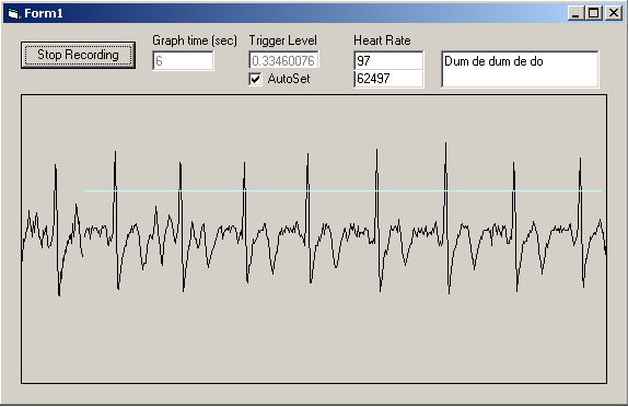
I think that an EEG needs a preamp stage with gain of 10,000 to bring a signal to 1V PEP which means instrumentation op-amps are probably the correct way to go, although here is an ECG built using TL-082s. I don't know how well it would work with another order of magnitude to it's gain, although an alternate resistor value in the schematic does enable this.

I don't really need a traditional waveform view of the EEG data, or I'd look at a soundcard-interfaced FM/AM modulated solution (which would also let me do FFT etc in software for a pretty spectral view).

For simplicity (ever my goal), not to mention isolation, I want a self-contained battery-powered unit. The best solution would have four meters/LEDs indicating the relative strength of delta, theta, alpha and beta waves. I *think* I could do this with bandpass filters after the preamp.

However I'm trying to think simpler still and find the minimum required to visualise, in some form, amplified brain waves. For one thing I don't have any instrumentation op-amps! The absolute simplest solution I can think of is having an analogue meter responding directly to the preamp, with a band-pass filter to knock out everything not +/- 3Hz of 10Hz. As meter movements can be so sensitive, that might let me get away with a lower-gain input stage - possibly using an LM324? Of course, a moving meter may not be a lot of use for practical neurofeedback, but it would be a good start.

Is my "ghetto solution" plausible or am I way off the mark on this one? Is a good enough "alpha wave filter" easy to do?

OK, I admit, the PICAXE connection is currently tenuous but I promise I'll find a way to shoehorn one in there!
 
Last edited:

MFB

Senior Member
Lots of analog conditioning required

Elektor Electronics had a couple of articles that included EEG circuitry (one that interfaced with a Gameboy) and I seem to remember they employed some pretty complex 50Hz noise rejection and AGC techniques. Not really a simple project.
 

Iain_C

Member
Most designs seem to be similarly complex but I have found some simple implementations (see esp. gameport-eeg.zip, RS232EEG_release010226.zip) that really go electrodes->preamp->single opamp bandpass filter->sampling stage and do the rest in software.

If I can hit upon a working preamp with bits I have I think I'm in business. Otherwise I'll have to order and play with some of those exotic opamps used in the schematics linked above (AD8221 etc)

I found an implementation of an LM324-based instrumentation amplifier used as a lab session in this online book (p48, Chapter 2), in an ECG application.

I've breadboarded that up and I'm having a play.

Any suggestions most welcome!
 
Last edited:

BeanieBots

Moderator
Well, I know nothing about ECG signals but the circuit published in your link is absolutely nothing special. It's not very high gain and there is virtually no filtering going on. If that circuit works, then I would be very confident that the same circuit using an LM324 would work just as well.
Frankly, I'm surprised that the published output is not swamped with 50/60Hz but maybe by taking a differential measurement it really does cancel out.
 

Iain_C

Member
BeanieBots, if you mean the first link to the EKGHappy site then I'm surprised it works too, if it does.

The amplifier in the online book is extremely sensitive but I haven't got it to track a heartbeat, and it's hard to visualise the output without plugging it into my scope, which I don't want to do for isolation reasons :/
 

papaof2

Senior Member
This is one of the few applications where the old Radio Shack ProbeScope (other companies sold it under other names, such as OsziFOX) would be very useful. It runs on 9-13 volts DC (9 volt battery for short periods), has a (very) small backlit on-board display, and can send the info via RS232 for display on a PC (use a laptop running on its battery for isolation). A laptop running on battery power can also be used as an isolated sound card-based scope (AC signals only).

I picked up a ProbeScope a couple of months ago for $35US (Craig's list has everything). It's a safe way to check presence/absence of signals in circuits that need to be isolated from mains and/or ground. If I need a *good* display of a signal (something better than the 5MHz bandwidth of the ProbeScope), then it's time to get out the Tektronix...

John
 

Iain_C

Member
I overcame that - finding 24mV at the probes with no discernible current in any direction I decided to trust my good old HP scope for 30 secs, but a front-end isolation unit is next on the table.

There is potential with this circuit but I haven't been able to stop it railing. I'll likely try this one next. ECG seems a sensible stepping stone to EEG; many of the circuits seem to use the same opamp configurations and differ only in gain and filter stages.
 
Last edited:

Iain_C

Member
Well, there's a lot of noise, and I'm an order of magnitude below where I need to be gain-wise. However, I've built the circuit described here and my results show a very clear path to an easy PICAXE-based heartrate monitor!

I'm going to do what I can to address the noise, and try to pile on more gain. I really want a probe scope!! Anyone in the UK with one in a cupboard, do make themselves known :D
 
Last edited:

BeanieBots

Moderator
Well that's a much better output than I would have predicted!
If all you want is the main pulse and don't mind some sloppy rise times, then simply fitting about 47nF across R12 will clean it up a lot.
You could try increasing R12 to 470k to double the gain but without offset-null on that op-amp it might saturate due to input offset at such a high gain.
Personally, I would go for making a band pass with IC3B and the spare IC3A leaving the front alone as it appears to work reasonably well. With good filter design it should then be possible actually reduce the gain and thus prevent any of the intermediate stages from going into saturation.
2n2 across both pairs of back-to-back diodes might also be worth a go to eliminate any high frequency stuff.
 

Iain_C

Member
BeanieBots, brilliant, that's exactly the sort of stuff I was hoping to hear. I'll try your suggestions. My deviations from the schem:

- 22uF caps from VDD to GND and from VDD2 to GND
- LM324N replaces IC1, IC2
- LM358N replaces IC3

(not the best opamps but they're the ones I had)

Also, I'm not even using matched resistors yet - these are all 5% tolerance.

Putting it in a nice metal box may help too!
 
Last edited:

Iain_C

Member
Just to add:

Personally, I would go for making a band pass with IC3B and the spare IC3A leaving the front alone as it appears to work reasonably well. With good filter design it should then be possible actually reduce the gain and thus prevent any of the intermediate stages from going into saturation.
- I'll try the other suggestions then implement an opamp bandpass if needed, but IC3A is used setting up the split rail VDD2.

2n2 across both pairs of back-to-back diodes might also be worth a go to eliminate any high frequency stuff.
- all three pairs :D
 

Iain_C

Member
Now cleaner - BeanieBots' filtering cap idea :)

Really much better than I thought possible with these components and surely an easy step to a PICAXE heart rate monitor. Onward towards EEG!
 

BeanieBots

Moderator
2n2 on all three pairs:D
The resistors are quite critical to maintain gain balance. The actual value is not very important but their ratios relative to each other are.
If you've got a load and and a DVM then hand pick for good match. Maybe even replace one of the 100k feedbacks with 91k+20k pot.
The LM324 gets a lot of stick but it's a great little work horse. My only issue with it is lack of offset-null but nothing a few electrons shoved up its back end wouldn't cure. If your supply is clean, then a pot between rails and high value resistor (10M) into -ve input should do it.
 

Iain_C

Member
BeanieBots, I'm going through all my 10K's and 100K's finding the best. R12 is already a pot; do you mean to allow gain control on one of IC1A/IC1B to better match them or on the mid-stage amp IC2B?

I'll add an offset trim pot too :)

Thanks for your continued analogue wizardy; I'm having trouble fully understanding the circuit as I can't seem to shoehorn it into the typical example. For example the top-left opamp doesn't lead to the righthand opamp's inverting input via a resistor.
 

BeanieBots

Moderator
I mean change R1 and/or R3 for a resistor plus pot that will give a small (1~2%) variation in gain for the differential inputs. It is essential that the gain of both stages is identical. The actual gain is not very important.
Don't be tempted to fit caps across R1 & R3. Although in theory, that would reduce bandwidth and cut the noise, in practice, unless the capacitor values are absolutely identical, the AC gains will differ slightly and will result in amplifying any AC common noise. The opposite of what you want!

Experiment with different capacitor values on the diode pairs. Again, the values need to be closely matched on each pair but should not be anything like as critical as in the feedback path. Slugging the final stage with a cap across R12 is not critical but you may need that offset control with higher gains.
If you can't get enough gain, then put another (AC coupled) stage after it. As mentioned earlier, that would be the best place for any filtering to be done.
Earlier filtering is technically better but in reality it is too complex to achieve as it requires very closely matched and critical value capacitors.
If you do opt for a high gain band pass filter, don't make the 'Q' too high.
If it is very high, the slightest bit of noise that comes through the common mode section will make it ring and you will think you have picked up a beat when there isn't one. A bit like a bell can be made to ring with its distinctive tone when in a very strong wind.
 
Last edited:

Iain_C

Member
BeanieBots, thanks again - I'll stick a couple of trimmers in series with R1 and R3 and see how matched I can get the diff inputs.

I'm thinking of trying a switched-capacitor IC filter as an extra stage, as I found in this gem kindly passed to me. I'll watch the Q, I'm familiar with ring modulation from audio engineering.

Analog Devices are kindly sending me some samples so I'll have "real" IAs to play with soon too.

IC filters and "real" IAs are against the spirit of this experiment though, I'm going to see just how far I can get with the venerable LM324 and keep learning loads of general analogue stuff in the meantime.

There's still the question of what happens to my pristine Vout when I get it, which is where the PICAXE comes in.

I'm thinking of trying to interface with my PC soundcard with FM modulation. For ECG reading the soundcard has enough bandwidth anyway, but the issue is that it cannot directly sample frequencies lower than 10Hz, which are required for EEG use. Perhaps I can get a PICAXE to vary a PWM output according to incoming ADC level and use some existing software from the soundcard EEG project.

Alternatively I can just chuck out ADC readings over the serial interface - easy way to add isolation too using an optoisolator. I'll have to figure out if there's enough bandwidth - I only need to sample at 60Hz as I'm only interested in 0-30Hz.

Hmm, given the negative swing on Vout does this mean I'll need to add a DC offset before the ADC? Or is there a better method of scaling Vout into something ADC-friendly?
 
Last edited:

BeanieBots

Moderator
It's easy to make the +/- swing 0-5v friendly.
You don't want any DC so just fit a largish (100uF -ve to OP) capacitor to the final output and feed that into a potential divider made from 47k/47k between 5v and 0v. Then feed the potential divider via another 22k into the PICAXE ADC input.
The divider will hold the level at 2.5v when there is no signal. The signal will pull that 2.5v up down via the cap which in turn will hold off any net DC component. The final 22k is to limit any current into the ADC should the voltage swing above 5v or below 0v.
 

Iain_C

Member
Thanks, that's brilliant. A result of my self-learning is I'm sketchy on some basic building blocks.

And here's the difference better matching of the diff amps makes - good enough to post inline :D


Onward to ADC experiments.
 

BeanieBots

Moderator
Well that's damn good clean trace:cool:
Both you and your circuit are looking healthy;)
Not sure what you plan to do with it next but the PICAXE should certainly be up for displaying rate or similar. If that is what you want to do, I'd probably go for some much heavier 'slugging' so that only the major spikes remain and then use a comparitor to square them up and feed into a digital input to be counted over time to give rate.
I doubt the PICAXE would be quick enough to read/detect the peeks using ADC measurements.
 

Iain_C

Member
Hehe :D

One 08M proto board later, your ADC interfacing advice having worked perfectly, it's now merrily sampling away and throwing data out over the serial port. That's all the PICAXE needs to do - the PC's going to read the data and do FFT on it.

Code:
main: 
	' Lather
	readadc10 1, w2
	
	' Rinse
	serout 0,N2400,(w2)   ' Two data bytes
	serout 0,N2400,(",")    ' Sync byte
	
	' Repeat	
	goto main
I'm cooking up a quick C# graphing thing to read and display the data so I can see how it looks when it comes in. If I can still get a clean ECG trace, that's the digital side done and the soundcard frequency response issue bypassed, and I can optoisolate the serial interface so the the whole thing's isolated.

Then I can further tweak the amp and see if I can get an EEG trace. Then, even if I have to upgrade the amp to "real" IAs the digital side should be fine to remain as-is.
 
Last edited:

MFB

Senior Member
Display serial data

Now you have reached the stage of transmitting clean serial data, why not consider using StampPlot Pro (free to download from www.selmaware.com) for a real-time PC display/log?
 

Iain_C

Member
Now you have reached the stage of transmitting clean serial data, why not consider using StampPlot Pro (free to download from www.selmaware.com) for a real-time PC display/log?
- Thanks, I wasn't really in a coding mood! StampPlot Pro should do perfectly for now. It looks really extensive and free is a LOT cheaper than LabView!
 

Iain_C

Member
OK, StampPlot pro is letting me get values in with the following code on the PICAXE side:

Code:
main: 
	readadc10 1, w1
	serout 0,N2400,(#w1)	' Two data bytes
	serout 0,N2400,(13)	' One sync byte (carriage return)
	
	goto main
I can still discern the ECG trace, but as you can see here it's all compressed into a very small dynamic range - note y-axis.

Although I can get a full 0-1000 sweep by tapping the electrodes together, I'm not seeing enough swing at the ADC input when the 'trodes are on.

Could this indicate I've lost gain? Before, I was taking the Vout output, and running it through my soundcard. The record level was up full - maybe giving me some gain I now don't have? If that's the case I suppose I'll be needing another gain stage..
 

Iain_C

Member
:( Turns out I'm only seeing a small swing at Vout. It hovers around 4.5V with a deviation of only +/- 0.2V.

So the PICAXE is behaving fine, but the earlier successes must have been down to the gain of the sound card.
 

Iain_C

Member
Another query if you'll indulge me!!

With reference to the original schematic, I see how IC1A and B are acting as a differential amp, and I can see how the outputs of IC2A and IC2B feed into each other in a circular feedback path.

So the gains of IC1A and B must be very well matched through R1 and R3; and the gain of IC2A and B must also be well matched - but by which resistors? R6 controls the gain of IC2B but which is the equivalent on IC2A? The 100K to VDD2?
 

BeanieBots

Moderator
IC2A & IC2B aren't quite the same as the others. They are AC coupled.
Both are (sort of) unity gain.
IC2A forms a slew rate limited (C1) non-inverting amplifier.
The gain is controlled by R7, R8 & R5. R9 sets the slew rate.
IC2B is in the more easily understood inverting virtual earth amplifier mode with R6 setting the feedback. However, it is not only R4 which supplies signal.
The slew rate limited (other polarity) signal is also fed in via R5 and the same gain (R5/R4 ratio).
Just as you get head around that, notice that the output of IC2B also feeds the other end of the R7/R8 junction which in turn is amplified by IC2A and fed back via R5 as described earlier.

In brief, R4 & R5 set the primary gains of that stage but I would be wary of attempting to change their gains for fear of upsetting the slew rate limit time constant. If you need more gain, then do it after (or at) the summing amplifier IC3B. Dropping R10 & R11 to 4k7 will double the gain.
Increasing R12 to 470k will give a further doubling.
At that level of gain, you will need offset control which could be done by varying the Vdd/2 input voltage to IC3B.

Hope that helps rather than confuses more.
DC offset can be remove with a cap into a potential divider as described in one of my earlier responses.
 
Last edited:

Iain_C

Member
That helps MASSIVELY, thank you for taking the time to interpret the guts of the circuit for me. I'll go through all that slowly and make sure I get it!
 
Top