DS18B20 errors?

moey

Member
I use a couple of DS18B20 temp sensors for my pool solar heating controller.
An 18X compares the roof sensor with pool sensor and turns the pump on&off when needed.

A couple of things I'd to ask the forum.
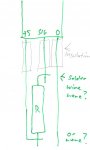
1. The cable length to the roof sensor is about 10m so you wouldn't expect much voltage drop. At first the roof sensor didn't work at all, as if it wasn't connected. After some experimentation, I found it would work ok only after I dropped the value of the DS18B20 pullup resistor to 2k2. Does anyone know why this might be?

2. Has anyone had any experience with DS18B20s occasionally delivering crazy readings, way above or below actual temperature. Normally I probably wouldn't have noticed because the next reading would overwrite the bad reading, but I store and display the day's min & max temperatures so the crook readings were quite obvious.

I wonder if this is caused by noise?, spikes? something like that. The sensors are cabling in screened data cable.
I have worked around the problem by taking two readings in a row and rejecting both readings if they differ. This works fine, no more odd readings displayed, but I just curious as to why.
 
Last edited by a moderator:

andrew_qld

Senior Member
1) Depending on what size cable you are using I would imagine there would be a fair bit of voltage drop at 5V over 10m. That could explain why the lower value resisitor worked.

2) I am guessing that the problem is data corruption due to noise (mains hum) or voltage drop. The best way of doing this is to use ballanced twisted pair cable that is not referenced to earth- although the sensor needs an earth so this could be hard.

Where is the 18x in relation to the sensors? And is the data only screwing up on the furtherest sensor or on both?


Update-
I have just found something on Peter Andersons site which talks about this. http://www.phanderson.com/picaxe/ds18b20_08m.html He suggests they should be OK run at up to 200 feet (60 odd meters) when run with the right cable..


Cheers,
Andrew
 
Last edited:

premelec

Senior Member
Not quite on your problem but AD590 type temperature sense units have a current to temperature conversion so lead resistance is not important [assuming you have enough voltage to drive the AD590 to its current]. Then you use the ADC function to get temperature - running the AD590 current through a resistor local to the PICAXE.
 

BeanieBots

Moderator
I doubt there would be any significant voltage drop and if the cable really is correctly screen there should be very little noise. It is likely to be cable capacitance which is also indicated by the fact that a lower pullup resistor helps.
Using lower values is OK but be careful that you not introduce self heating in the sensor whenever it is read.
I'd put a resistor (4k7) on BOTH ends of the wire and a cap (100nF) on the supply at the sensor end.
 

Hooter

Senior Member
DS18b20

If I recall correctly, quite a while ago there was a faulty batch of DS18b20's released from the manufacturer. A search of previous forums may show the batch numbers or someone who contributed may remember.
 

BeanieBots

Moderator
That was a few years ago now but I guess a few might still be floating around. Also, very early firmware did not wait the full 750mS required for a conversion. However, I don't think either of those issues are to blame here because the fault would result in returning the temperture of the previous start conversion and not some erratic number.
 

MORA99

Senior Member
The DS should return 85 if its an error, but I have been getting 129C too on short cable (<3M) lengths, its just one or a few reads then its normal again.
 

Cruiser

Member
The DS18B20 actually generates a CRC check byte which should be read along with the Temperature LSB and MSB bytes. However, I don't think the PICAXE does this or if it does, it takes no action if the CRC doesn't match. I've been able to corrupt the temperature data enough to get ridiculous readings (not just wrong but well outside the DS18B20's range) and the PICAXE happily passes them on.

It would be better for long or noisy cable runs if the CRC was re-calculated and checked during each ReadTemp command but I guess that would take up a significant chunk of firmware.

I can only suggest using shielded cable and good connectors. I was originally using 3.5mm stereo connectors for hooking up my DS18B20 probes but they proved unreliable. I'm now using Mini-Din (S-VHS) connectors and they work great.
 

leftyretro

New Member
I recently added a DS18B20 to parts purchase I made online. I hooked it up to my solderless breadboard with a 28X1 and wrote a simple program to send the temp value to a serial LCD display I use with my breadboard.

The sensor worked fine and the value seemed realistic, however I did notice that about every 10-12th reading would be a real jump in value, returning to normal the next reading. I didn't investgate further, but it would seem that one might consider taking the average of several samples or read the CRC error checking if each sample is critical.

Lefty
 

inglewoodpete

Senior Member
I use several DS18B20s in my house as sensors for solar space heating. The hardware involved is unshielded twisted pair (UTP) telephone cable (about 11 metres) with RJ12 connectors. The DS18B20s have a capacitor (0.22uF from memory) connected across the supply rails, close to each sensor. Otherwise, I use the 3-wire connection setup described in the command manual.
 

moey

Member
I haven't tried adding caps at the sensor end. Will try it and see what happens.
Meanwhile, comparing two readings in a row seems to be catching errors - haven't had bad reading displayed for days.
 
Last edited by a moderator:

Michael V

Senior Member
What is the code?

I want to add temperature measurement to my event data logger fitted to a large mining excavator. I didn't particularly wast to use $100 temperature probes, easily destroyed in the environment, when the DS 18B20 would do it. (plus i already have one).

I was concerned about the cable run (in my case about 8m with 600 Tonnes of steel around) and possibility of recording false readings. The answers are in this thread, almost. Use screened cable and capacitor at the sensor end, plus read the data sheet. I was concerned about the 750 ms holding up proceedings, but in another thread OWIN and OWOUT on 28x1 will buy me some breathing time to do other things, if i need it. So DS1820B is back on the agenda.

I would like to know more about is the code that checks consecutive readings for consistency, or how to use this CRC code to ensure the correct reading has been recorded.

Does anyone have any easily understandable code to share?

Also, what is the best way of protecting this little thing from destruction, do you encapsulate it in epoxy? For the cost of these things i don't mind putting them in harms way, so i can at least get data in the short term till they get smashed.
 

moey

Member
To compare two readings I just save the first one, take another and then start again if they don't match.
There's probably a more elagant way to do it, but this seems to work fine for me.
It uses up two Word vaiables but I can reuse them later in the code anyway.

Main:
READTEMP12 6,Tfirst 'read DS18B20
READTEMP12 6,Tsecond 'read again
if Tsecond <> Tfirst then Main 'if two readings don't match then do it again
 
Last edited by a moderator:

Michael 2727

Senior Member
@ Michael V, dropping the pullup resistor value is listed
in the Dallas/Maxim application notes as a fix for long/noisy
cable runs (app notes on the One Wire Network & Assoc files)
There are several sheets of info, you'll have to search their site.

Plain old Readtemp (vs Readtemp12 ) should be ok for Auto/Plant
equipment monitoring.

Re: Enclosure, I nearly posted this the other day-
Sitting on the front step feeding the chooks the
other day, I noticed some spent .22Mag casings.
I live on a farm BTW, I thought these would make
a very neat housing for a DS18B20.
Brass Case 5.7mm ID x 26.6mm (1") long.
A DS18B20 is 4.5mm DIA.
Has integral mounting/locking ridge :)

You could put a small blob of heat conducting compound
in the bottom, insert a DS chip with attached wires/insul
then fill up the rest with Epoxy or Silicon sealer etc.

If you want a couple I could mail you some, message me.
 

Michael V

Senior Member
Of course

Thanks Moey - That code is amazingly simple, i was expecting to have some sort of tolerance to be built in to allow for acceptable fluctuations, but i guess if the device is set to measure to the nearest degree than that will be OK, as long as time is not a factor.

M2727, the '22 shells would probably be good, but that might freak the customer out, being a mine and not a farm they might be a bit sensitive. Plus, if my project succeeds i want to export it globally. But i'll give it some thought.

While researching this and looking at other threads i also came across the LM35, or if i get it at Jaycar it is the LM335, linear temperatures sensor in a similar TO92 package to the DS18B20 (although the web site has the wrong picture). The data sheet talks about encapsulating it in shrink wrap, so i might try that.

But now, on the subject of the LM335, which delivers a predictable 2.98V at 25C and 10 mv/C, can be calibrated, why not use that? Picaxe literature seems to prefer the DS18B20, there must be good reason. It it for convenience and ease of use, -eg there is a nice simple "readtemp" command, or are there other advantages?

It is also less than half the price, not that that is an issue, the DS18B20 is cheap enough.
 

BeanieBots

Moderator
The simple difference is digital vs analogue.
When running off 5v and using ReadADC10, the PICAXE will have a resolution of about 5mv. That's +/- 0.5C compared to +/- 0.06C for the DS18B20. (readtemp12)
Also, it wouldn't take much noise to introduce 10mv of 'crud' onto a long cable run.
The LM35 could be made to give better resolution/accuracy than a DS18B20 but it would take careful design, op-amps and a reference controlled power supply. The DS18B20 simply needs a pull-up and one pin.
Don't forget, ADC with a PICAXE is only as good as your power supply.
 

Michael V

Senior Member
That Explains it

Thanks BB - i suspected, but that explains it. Looks like i'm sticking with DS18B20 and readtemp, and (future project) learning to use owin and owout!
 

Michael V

Senior Member
Resistors at both ends - Soldering Skill?

In going through all the threads the idea of using Cat 5 Flexible cable turned out to be the most appealing, with the twisted pairs providing shielding. It is also about a third of the price of the screened cable i used for the pressure transducers

One pair for G and +5 and the other for signal and G, with the second G only connected at the picaxe end. I also followed BB's advice of putting a resistor at the sensor end, it seems to make sense, and clearly works. Seems to provide consistent results, but i will still use Moey's code as well.

It took me about half and hour to solder the cable, tiny chip leads and resistor together, and the result is not pretty, angular and lumpy, still looking fragile. AAAAH. It looks better all wrapped up in shrink wrap though. I want to put together a few more of these. I like the result, and at only $4.44 per sensor and $3.44 for post they are a good buy, (the cable is more expensive).

Does anyone have any tips about how to easily connect in the resistor at the sensor end?

Also, the Cat 5 cable has four pairs, and i'm only using two. What should I do with the other two? Should i just cut them off (as i have done) or connect them to ground? What is considered best practice?
 

BeanieBots

Moderator
Cut the signal pin so that the others are just a bit more than the resistor body length longer. Cut the resistor legs so they are only 3mm long.
Make a 2mm 90deg bend on the 0v line and one end of the resistor.
Strip some insulation off the cable and slip it over the legs exposing only a few mm of leg.
It should now be possible to solder the resistor in place with all legs straight and no strain. Don't twist or fold the wire. Keep leg and wire flat against each other for about 3mm.
Connect any unused cores to 0v.

The whole unit can then be epoxy'd into 1/4" stainless tubing.
 

Michael V

Senior Member
Is this Right?

Hi BB,
Form your description i think i know what you mean about the short leads and bends. Much smarter than my method. But still not 100% sure. Also, you have the resistor going to ground, and i think it should be going to +5.

Would you please check the attached sketch?

Does the wire get soldered half way up the leg? I was doing it on the end.

MV
 

Attachments

BeanieBots

Moderator
Yes, I was wrong earlier, the resistor should be between signal and 5v.
Your sketch is correct.
Rather than have the leads cross each other, I found that if you bend them such that they lye parallel to each other, the solder joint can be made very small and neat. I've done this several times now and each one gets a little better with hindsight knowledge. If you can get hold of the very small 1/8W resistors it helps. I've never tried with surface mount but would guess they would offer optimum space saving.
Dip the whole assembly in epoxy and then slip it into a short length of stainless steel tube. Makes a very robust assembly. I have one which also incorporated silicon air line over the cable which has been happy under 3 foot of water for the last three years.
The DS18B20 itself WILL suffer water ingress over time if used in wet conditions, so it is important to make sure it is well coated with epoxy, varnish or similar.
 

Michael V

Senior Member
ReadTemp, OWIN, OWOUT - Confusion

Hi Guys,

Now that I am a DS18B20 disciple i want to squeeze the most out of ithese little gizmos.

I want to exploit the feature of the DS18B20 and the 28X1 commands to use Owin and Owout. This is not for any accuracy purpose, rather than to take advantage of a known time delay of about 3-4 seconds, start the reading at the beginning of it and read the temperature without delay at the end of it. This will eliminate the 750ms delay due to readtemp. More here: http://www.picaxeforum.co.uk/showthread.php?p=55007#post55007


I used the code exactly as in the manual, except a different pin number:
Code:
owout 1,%1001,($CC,$44)
&#8216; send &#8216;reset&#8217; then &#8216;skip ROM&#8217;
&#8216; then &#8216;convert&#8217; then apply &#8216;pullup&#8217;
pause 750 &#8216; wait 750ms with strong pullup
owout 1,%0001,($CC,$BE)
&#8216; send &#8216;reset&#8217; then &#8216;skip ROM&#8217;
&#8216; then &#8216;read temp&#8217; command
owin 1,%0000,(b0,b1) &#8216; read in result
sertxd (#w0) &#8216; transmit value
But the result that i got was not what i expected. I started playing with the variables and became more confused. Then i refined some code just to focus in on the readtemp and OWIN/OWOUTcommands:
Code:
#picaxe 28x1

' ********************
' ***** Symbols  *****
' ********************

'Symbol definitions
symbol data0 = b0
symbol data1 = b1
symbol data2 = b2		'(b10 + b11)
symbol data3 = b3
symbol dataw2 = w2 '(b4 + b5)
symbol dataw3 = w3     '(b6 + b7)


main:

pause 1000
owout 2,%1001,($CC,$44)		&#8216; Start the temperature read
					&#8216; send &#8216;reset&#8217; then &#8216;skip ROM&#8217;
					&#8216; then &#8216;convert&#8217; then apply &#8216;pullup&#8217;
	pause 750


owout 2,%0001,($CC,$BE)	&#8216; Complete the temperature reading
				&#8216; send &#8216;reset&#8217; then &#8216;skip ROM&#8217;
				&#8216; then &#8216;read temp&#8217; command
owin 2,%0000,(b6,b7) 	&#8216; read in result to dataw3


	readtemp 2,data1	'Read Temp (Includes delay)
	pause 30

'Display change onPC
	sertxd ("Readtemp ",#data1," Temp W1 ",#dataw3," Temp B6 & B7 ",#b6,#b7,13,10)	

goto main
Using this code, at room temperature of 23C, readtemp gives me 23C, the word variable dataw3 derived from Owin and Owout gives me 369 or thereabouts, and b6 and b7, which are supposed to make up w3, gives me 11 and 41. Same numbers when i convert BCD to ASCII for display on LCD via I2C.

So what is happening?

I looked at the data sheet for The DS18B20 and i can't figure it out. I looked at Readtemp 12 in the manual, meant to be similar to Owin and Owout, and it didn't help. The "One wire Tutorial" referred to in the manual OWIN and OWOUT pages is nowhere to be found.

So how do I do it? Is there just a factor that i use to convert, or some other magic?

And also - this may be unrelated, when i run the program on Simulator it locks up on the first OWOUT command line.

Michael
 
Last edited:

BeanieBots

Moderator
You are getting the correct result.
The owin command returns the raw data.
To get degC, simply divide by 16.
If the temperature is negative, there is another recent thread which explains how to interpret the returned number.
 

Michael V

Senior Member
Too Easy!

Thanks BB, I'm glad it was that simple.

I don't understand the significance of the 16, maybe a hex thing. Anyway, after some fooling around with my Picaxe maths i worked it out.

This is part of the code:
Code:
' Capture the data
	
	readadc 0,data0	'Pressure Tank
	pause 30
	readadc 1,data1	'Pressure Return Manifold
	pause 30
	
	let temp_byte = data1 - data0
				'2 bar = 256
	dataw2 = temp_byte*200/256	'Pressure in Bar x 100 = kPa
	

owout 2,%0001,($CC,$BE)	&#8216; Complete the temperature reading
				&#8216; send &#8216;reset&#8217; then &#8216;skip ROM&#8217;
				&#8216; then &#8216;read temp&#8217; command
owin 2,%0000,(b6,b7) 	&#8216; read in result to dataw3

dataw3 = dataw3*100/160	&#8216; converts word variable into temp X 10

	'readtemp 2,dataw3	'Read Temp (Includes 750ms delay - Fallback)
	pause 30


'Convert DP word variable to ascii
	bintoascii dataw2,temp_byte1,temp_byte2,temp_byte3

'Write DP to PC
	sertxd ("DP ",", ",temp_byte1,".",temp_byte2,temp_byte3,", ")

'Send DP  to Logomatic
	serout 4,T2400,(temp_byte1,".",temp_byte2,temp_byte3,",")

'Display DP Data on Modtronix LCD.
	writei2c  ($8a,2,1)	'goto row 2 pos 1	
	writei2c  ($80,"Bar:")
	writei2c  ($80, temp_byte1,".",temp_byte2,temp_byte3)
	
'Convert Temperature word variable to ascii
	bintoascii dataw3,temp_byte1,temp_byte2,temp_byte3

'Write Temperature to PC and go to new line
	sertxd ("Temp ",temp_byte1,temp_byte2,".",temp_byte3,13,10)

'Send Temperature  to Logomatic and go to new line
	serout 4,T2400,(temp_byte1,temp_byte2,".",temp_byte3,13,10)

'Display Temperature  Data on Modtronix LCD.

	writei2c  ($80,"Tmp:")
	writei2c  ($80, temp_byte1,temp_byte2,".",temp_byte3)


	Pause 250
	writei2c  ($80,$0d)	'0x0d =  first line
	writei2c  ($80,"Boom Low      ")	


'*** At this point test for time condition


'**** if met, save the data go to a subroutine

goto main
Cogniscant of the lessons in picaxe maths in other threads, i first multiplied by 10 before dividing by 16, saving some integer accuracy. The intention is to send the data both to I2C LCD and to external data logging via serout. Other pressure data also retains a factor of 10.

Rather than use the #prefix i have used the clever BINTOASCII command, making use of temporary variables. This allows me to insert a decimal point before the last digit, so i can export actual Bar (pressure) and Celcius to 0.1 C (roughly) and give more accuracy in the display, more impressive and "real". Very clever. I think I like OWIN and OWOUT now.

Thanks heaps once again! (home others are learning from my waxing lyrical)

Michael

PS - and the simulator still crashes on the first Owout line
 
Last edited:

tikeda

Member
See the thread titled: "readtemp12 negative values"

The lowest 4-bits of the 2-bytes returned from the DS18B20 are fractions of degrees C. Dividing by 16 shifts those bits out (sending them into digital heaven somewhere), leaving a whole number of degrees. Note that this method doesn't provide any rounding and so a measured 21.9375 degC will end up as 21 degC, not 22 degC.
 
Last edited:

Michael V

Senior Member
But it works ?

Hi Tikeda,
Thanks for the comment, but i'm not sure we are understanding each other.

I understand that if i divide by 16 then the least significant parts disappear into digital heaven, and i'm left with the lower degree C (truncated). However, i'm not doing that.

I'm really only dividing by 1.6, and then cleverly using BINTOASCII to separate the value into individual integers, then adding a decimal point to the sertxd, serout or I2C output so that it appears to have been divided by another 10, giving a more precise temperature value. for future analysis. This appears to preserve a much greater degree of accuracy, if you watch the PC display, certainly 10X that of dividing by 16, which should be enough. It is convenient and easy to do.

Fortunately for me the machine will never cool to below 0C, which the ambient might be for 5 nights in a year, so i don't have to worry about negative values just yet.

Thanks,
Michael
 
Last edited:

tikeda

Member
OK, I'm following you now, Michael. Your multiplication factor is 10/16.
If the chip measures 8.75 deg, the bit pattern in the returned word is:
#0000 0000 1000 1100 ( = 140 decimal)

Multiply by 10:
#0000 0101 0111 1000 ( = 1400 decimal)

Divide by 16:
#0000 0000 0101 0111 ( = 87 decimal)

BinToAscii (not BCDToAscii) returns: "0", "0", "8", "7", which is approximately 10x 8.75.

The 1/16th factor comes into play because the lowest bit returned by the DS18B20 corresponds to 1/16th of a degree. The non-fractional portion of the binary number returned by the sensor is shifted four bits up (e.g. from the above example that is why 140/16 returns the actual, decimal temperature of 8.75 -- As BeanieBots mentions). Multiplication by ten ensures that you return tenths of degrees as integers. Division by 16 shifts right (and out) the remaining, fractional, binary components.

You may want to change this line:
Code:
dataw3 = dataw3*100/160
...to....
dataw3 = dataw3*10/16
...because at 45 C (hot, but not outrageous), multiplication of the returned data by 100 will exceed the capacity of the word-sized variable (45 C would return as 45*16 = 720 decimal, and 720*100 = 72,000). Word variables are good up to 65,534. The current code will produce odd results at temperatures over 41 C (106 F). The lower line should work from 0-125 C.
 
Last edited:

Michael V

Senior Member
Good Advice

Thanks Tikeda,
You were right, i checked my code and it actually is BINTOASCII. I'll have to go back and edit that.

I thought 100 was OK and in fact desirable for integer accuracy because the number being returned on the screen with #prefix was 369 at 23C. But now you mention i do expect to measuring around 60 or 70 C.

So you have saved me more problems.

So i'll go with

Code:
dataw3 = dataw3*10/16
or maybe cut loose and use

Code:
dataw3 = dataw3*20/32
As i may have mentioned, if it ever gets to 100C the machine will be on fire, and no one will be thinking about the Picaxe.

Thanks once again, I don't know where i'd be without this forum.

Michael
 

tikeda

Member
Yeah, I've learned tons of information by browsing through these topics. I think this is one of the best forums of this type that I've encountered. Extremely helpful, good natured folks here.
 
Top