I bought a CRO. Suddenly it is possible to debug all sorts of problems!
1) The "1000m" units work but I'm having trouble getting more than 80 metres range. I suspect it is the high tension powerlines only 300m away.
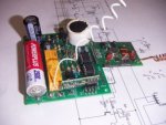
2) The "4000m" units work better. But they draw 200mA at 9V and the capacitors needed to store a charge for a packet transmission are getting too big. I have moved over to 8 NiMH batteries in series giving 9-10V. I found some neat 4.5V 50mA solar modules on ebay out of Hong Kong - they cost about $4 each and 3 in series work well charging the batteries. 50mA charging a 600mAH NiMH comes in at trickle charge rates so no electrolyte is lost. Thus complex charging circuits are not needed. The volts are divided by 3 (200k/100k) and the picaxe monitors the volts. I also tapped off the midpoint of the battery and divided that by 3 as well so as to detect any reverse batteries and put the picaxe into low power mode until morning if the batteries are going flat.
3) Layout is absolutely critical. The Rx module is happiest if its antenna is surrounded by air and no wires of any kind. So the antenna sticks out the bottom of a 1.2m length of 90mm downpipe. The Tx unit seems to need to be at least 1m away from the rest of the circuit. I've used 1m of 3 wires - 9V, Gnd and data. I suspect the 1m means this is forming the earth of a dipole. But officially a dipole should be 1/4 a wavelength but that put the Tx too close to the picaxe causing it to reset. Next thing - the wire must be absolutely straight. I was stuffing it into a 50cm piece of downpipe and the coils in the wire made the Tx signal completely disappear. RF truly is a black art and a CRO has helped so much. Best $120 I have spent in a long while. So I've got about 1.2m of downpipe with everthing in it to keep it waterproof.
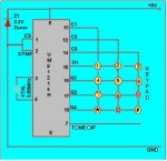
4) Some interesting experiments with DTMF, sine waves and pulse coding. First, sending a square wave into a Tx module gives a square wave out as expected. But sending a sine wave biased at 2.5V also gives a square wave out. The Tx units seem to have threshold detectors at about 1.5 and 3.5V. Second thing - putting 0V into a Tx gives 0V out. Putting 5V gives 5V out but it goes to 0V after 0.1 second. So the minimum frequency these units can transmit is about 10Hz. Third experiment - how do the signals fail. They seem to fail with pulse widths getting narrower and a square wave ends up being just narrow pulses. Hence sending data will get corrupted. So I tried sending a 1Khz tone and detecting it with an op amp 2nd order bandpass filter and an op amp rectifier. This doubled the range but the baud rate went down to about 8 baud or 1 bit per second. I tried two circuits - a 100Hz/2Khz dual tone system but the narrowing pulse width meant the 100Hz tone failed too early. Then I tried a simple 1Khz tone with simple on/off. A low pass filter with a cutoff of about 0.1hz detected the average value and with a series of 01010101s at the beginning to bias the low pass filter it was possible to extend the range to double. Detecting frequency at this range is not possible - there are too many spurious spikes so all DTMF/phase lock loop solutions no longer work. I am concluding that the very slow speed does not justify the doubling of range.
Have posted a new schematic at
http://drvernacula.topcities.com/315_mhz_solar_powered_radio_rptr.htm at the bottom of the page. Design is now getting quite simple - 1 metre of 90mm downpipe with the Tx sitting in the top on 1m of wire. The batteries and board sit at the bottom with the antenna for the Rx sticking out the endcap through a small hole. Two wires going to the 3 4.5V 50mA solar panels coming out the bottom. All mounted on a 2m wood stake which is tied to either a fence post or a star dropper. This gets the Tx about 3m off the ground which makes a big difference to the range.
 25.1 KB Views: 347
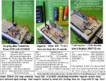
")