Meet Scooter Boy. From the same stable as Hybrid Trotter but with the leg modules reversed for the human knee action.
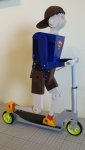
A block of two 55g servos drive the active leg, one 9g steers, and one 55g is packed into the torso with all the electronics. A 2S 1.0A Lipo is built into the footplate with its monitor/alarm. One 5A SBEC almost satisfies the peak servo current and one 3A UBEC keeps the rest of the electronics separate. Construction is mainly 2mm plywood, plus silicone section from a kitchen shop for the all-important feet. Just the right amount of ankle/toe flexure and perfect grip on a smooth surface. The foam tyre landing wheels are in character, but the all-up weight of 664g can flatten them and then they wobble.
[video]https://youtu.be/59S8kIDhQpM[/video]
Originally a 20X2 project, it soon became apparent that some form of active control was needed to keep this bot upright. I had hoped that steering into the fall would be enough – no chance! As soon as the active foot applies a backward/downward thrust, this 40cm tall asymmetric bot topples sideways. Hence the added torso movement to compensate.
Having investigated the MPU 6050 using both a 28X2 module and a Nano V3 CH380G at
I set the FIFO to output roll data every 30mS which leaves plenty of time to calculate and apply the next servo refresh values. Writing a routine to capture 64 time slots of roll and servo values during movement, the screen output was copied into an Excel spreadsheet for analysis. Graphing two seconds of moving bot clearly showed exactly when it leans or topples. Fixing things was much more difficult.
Attempting to tune a suitable PID controller by trial and error was quite unproductive. Eventually I managed to convert the data collection routine to test the PID step-response whilst stationary. Then it became very clear. Intuitively, if this bot leans left then moving the mass of the torso to the right should rectify the lean. It does not, even worse it assists the fall. This is like using a screwdriver in space: there is no ground reference. So when the torso moves right, the rest of the bot moves to the left. Eventually the masses sort themselves out but the damage is done.
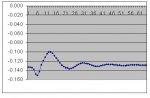
This is a plot of radians against time (30mS grid). The PID is switched off and the torso servo is stepped 0.1mS (not a lot). It shows that the bot moves the wrong way first then settles down.
So a bit of a setback for this project but lots of new tricks for next time. It might be possible to animate the rear axle to achieve a ground-referenced torque. Too late for this model – it’s been rebuilt too many times over the last six months.
Back to the Picaxe beginning. All I could manage was to use the graphic running data and manually tune the bot to perform a straight push within its stability limits. As such it could use lookup tables and run entirely on the 20X2. Two or more consecutive pushes and it reaches a good speed but will crash.
So now the Nano V3 runs most things but it couldn't cope with the IR input. It does have a nice ‘interrupt on change of pin state’ but any Interrupt Service Routine (even an immediate return) upsets the microsecond system clock. Fine if you simply print the IR button value to screen but useless if clocking out servo times. IR pulse widths of 0.6 to 2.4 mS constantly conflict with servo pulse widths of 0.75 to 2.55 mS. If interrupts are not used then the message length of the IR and the delay to ensure the key is no longer depressed is too slow for the main cycle time of 30mS.
Solution – use a 08M2 to handle the IR. There was no room for a larger chip which could slave onto the I2C bus with the MPU. The 08M2 has just enough pins to output two nibbles of data but how to control the transfer? The IR data is only 7 bits so one pin is set tristate and doubles as a flag. When a character is ready the flag is raised. When polled every 30mS, the first 3 bits are read and the flag is pulled low by the Nano; then the next 4 bits are read.
A block of two 55g servos drive the active leg, one 9g steers, and one 55g is packed into the torso with all the electronics. A 2S 1.0A Lipo is built into the footplate with its monitor/alarm. One 5A SBEC almost satisfies the peak servo current and one 3A UBEC keeps the rest of the electronics separate. Construction is mainly 2mm plywood, plus silicone section from a kitchen shop for the all-important feet. Just the right amount of ankle/toe flexure and perfect grip on a smooth surface. The foam tyre landing wheels are in character, but the all-up weight of 664g can flatten them and then they wobble.
[video]https://youtu.be/59S8kIDhQpM[/video]
Originally a 20X2 project, it soon became apparent that some form of active control was needed to keep this bot upright. I had hoped that steering into the fall would be enough – no chance! As soon as the active foot applies a backward/downward thrust, this 40cm tall asymmetric bot topples sideways. Hence the added torso movement to compensate.
Having investigated the MPU 6050 using both a 28X2 module and a Nano V3 CH380G at
I set the FIFO to output roll data every 30mS which leaves plenty of time to calculate and apply the next servo refresh values. Writing a routine to capture 64 time slots of roll and servo values during movement, the screen output was copied into an Excel spreadsheet for analysis. Graphing two seconds of moving bot clearly showed exactly when it leans or topples. Fixing things was much more difficult.
Attempting to tune a suitable PID controller by trial and error was quite unproductive. Eventually I managed to convert the data collection routine to test the PID step-response whilst stationary. Then it became very clear. Intuitively, if this bot leans left then moving the mass of the torso to the right should rectify the lean. It does not, even worse it assists the fall. This is like using a screwdriver in space: there is no ground reference. So when the torso moves right, the rest of the bot moves to the left. Eventually the masses sort themselves out but the damage is done.
This is a plot of radians against time (30mS grid). The PID is switched off and the torso servo is stepped 0.1mS (not a lot). It shows that the bot moves the wrong way first then settles down.
So a bit of a setback for this project but lots of new tricks for next time. It might be possible to animate the rear axle to achieve a ground-referenced torque. Too late for this model – it’s been rebuilt too many times over the last six months.
Back to the Picaxe beginning. All I could manage was to use the graphic running data and manually tune the bot to perform a straight push within its stability limits. As such it could use lookup tables and run entirely on the 20X2. Two or more consecutive pushes and it reaches a good speed but will crash.
So now the Nano V3 runs most things but it couldn't cope with the IR input. It does have a nice ‘interrupt on change of pin state’ but any Interrupt Service Routine (even an immediate return) upsets the microsecond system clock. Fine if you simply print the IR button value to screen but useless if clocking out servo times. IR pulse widths of 0.6 to 2.4 mS constantly conflict with servo pulse widths of 0.75 to 2.55 mS. If interrupts are not used then the message length of the IR and the delay to ensure the key is no longer depressed is too slow for the main cycle time of 30mS.
Solution – use a 08M2 to handle the IR. There was no room for a larger chip which could slave onto the I2C bus with the MPU. The 08M2 has just enough pins to output two nibbles of data but how to control the transfer? The IR data is only 7 bits so one pin is set tristate and doubles as a flag. When a character is ready the flag is raised. When polled every 30mS, the first 3 bits are read and the flag is pulled low by the Nano; then the next 4 bits are read.