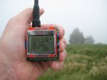
I have been working on the GPS locator to add the ability to receive, by data telemetry the GPS data from the remote transmitter.
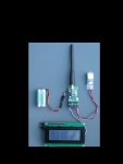
SMA sockets for the antennas have been added and this has improved the range, cheap SMA UHF antennas easily found on eBay can be used as well as simple bits of wire.
The smaller PCB is intended for use in a model aircraft and will (using the attached GPS module) establish a home fix and from then on transmit data telemetry for the Latitude and Longtitude, Distance and Direction from home, home altitude and AGL, as well as battery volts and temperature. An AXE132 Serial LCD driver PCB and 20x4 display can be attached and will give a running picture of GPS location and distance and direction from home. The battery pack shown is 4 x AAA Nimh.
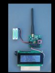
The larger PCB is designed as a 'Groundstation' and uses mostly pin in hole components to make it easy to assemble. There is a header to take a OPENLOG logger (the small red PCB) and an expansion connector for connecting a GPS, AXE132 Serial LCD for display and other stuff. The logger records all the received telemetry to a micro SD card such that there is a PC readable log or track of where and how high the transmitter has been.
Both PCBs use a 28X2 with a common pin use such that the programs for either PCB are interchangeable.
Line of sight range, such as between a groundstation to an in flight model aircraft or balloon, is difficult to predict without actual testing on a balloon. I did some line of sight tests with the earlier modules between distant hilltops, where a range of 8kM was achieved with 12mW, with some packets received with as low as 3mW. The better antenna arrangement of these newer modules already shows a reasonable improvement on this, such that the line of sight range should be in excess of 40kM using the modules full 100mW and simple vertical antennas. There is still scope for further improvements by tweaking the settings of the RFM22 transmitter.
The modules can still transmit the 'telemetry' as 15WPM or 60WPM morse, all you need to receive that is a UHF transceiver and a PC with soundcard to decode the morse. I have also built a standalone morse decoder which will be the subject of another post.
Code to follow, its working, but needs a thorough review to add suitable comments etc, before I forget what does what and why.
SMA sockets for the antennas have been added and this has improved the range, cheap SMA UHF antennas easily found on eBay can be used as well as simple bits of wire.
The smaller PCB is intended for use in a model aircraft and will (using the attached GPS module) establish a home fix and from then on transmit data telemetry for the Latitude and Longtitude, Distance and Direction from home, home altitude and AGL, as well as battery volts and temperature. An AXE132 Serial LCD driver PCB and 20x4 display can be attached and will give a running picture of GPS location and distance and direction from home. The battery pack shown is 4 x AAA Nimh.
The larger PCB is designed as a 'Groundstation' and uses mostly pin in hole components to make it easy to assemble. There is a header to take a OPENLOG logger (the small red PCB) and an expansion connector for connecting a GPS, AXE132 Serial LCD for display and other stuff. The logger records all the received telemetry to a micro SD card such that there is a PC readable log or track of where and how high the transmitter has been.
Both PCBs use a 28X2 with a common pin use such that the programs for either PCB are interchangeable.
Line of sight range, such as between a groundstation to an in flight model aircraft or balloon, is difficult to predict without actual testing on a balloon. I did some line of sight tests with the earlier modules between distant hilltops, where a range of 8kM was achieved with 12mW, with some packets received with as low as 3mW. The better antenna arrangement of these newer modules already shows a reasonable improvement on this, such that the line of sight range should be in excess of 40kM using the modules full 100mW and simple vertical antennas. There is still scope for further improvements by tweaking the settings of the RFM22 transmitter.
The modules can still transmit the 'telemetry' as 15WPM or 60WPM morse, all you need to receive that is a UHF transceiver and a PC with soundcard to decode the morse. I have also built a standalone morse decoder which will be the subject of another post.
Code to follow, its working, but needs a thorough review to add suitable comments etc, before I forget what does what and why.
Attachments
-
 182.8 KB Views: 258
 -
 114.1 KB Views: 197
Last edited: