Yes, again with the matrix keypads...
")
I searched the forums and found several threads, and some very useful code posted by hippy, I think it was, using the 20X2 and a lookup table.
Here is the code to save you looking for it:
I'm planning on basically using this code, but with an 18M2+ and it's B port.
Do you see anything inherently wrong with that concept?
I don't suppose I could use a 14M2?
It does not have enough pins on any ONE port, but I don't suppose you can split the operation across both ports on the 14M2?
Along the lines of rows on portB, columns on portC kind of thing?
I suspect NOT, as the codes I have seen for matrix decoding, seem to rely heavily on being able to read the state of the whole port in one command as an important step in the code.
...but then, I often misunderstand things...
I searched the forums and found several threads, and some very useful code posted by hippy, I think it was, using the 20X2 and a lookup table.
Here is the code to save you looking for it:
Code:
#Picaxe 20X2
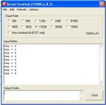
#Terminal 38400
#No_Data
' 20X2
' .---__---.
' |+V 0V|
' |SI SO|----------------------> TXD
' |C7 B0|<-----------.
' |C6 B1|<---------. |
' |C5 B2|----> * * * * 1x1 through 4x4
' |C4 B3|----> * * * * Matrix Keypad
' |C3 B4|----> * * * * No Diodes
' |C2 B5|----> * * * * No Resistors
' |C1 B6|<-----' |
' |C0 B7|<-------'
' `--------'
Symbol DIR_X = %00111100
Symbol MSK_X = %11000011
Symbol XOR_X = MSK_X
Symbol DIR_1 = %00100000
Symbol MSK_1 = MSK_X
Symbol XOR_1 = MSK_X | DIR_1
Symbol DIR_2 = %00010000
Symbol MSK_2 = MSK_X
Symbol XOR_2 = MSK_X | DIR_2
Symbol DIR_3 = %00001000
Symbol MSK_3 = MSK_X
Symbol XOR_3 = MSK_X | DIR_3
Symbol DIR_4 = %00000100
Symbol MSK_4 = MSK_X
Symbol XOR_4 = MSK_X | DIR_4
Symbol keyPress = b2
Symbol lastKeyPress = b3
; ===================================================
SetFreq M32
PullUp %11011000
lastKeyPress = $FF
Do
Gosub ReadKeyPress
ReadTable keyPress, keyPress
If keyPress <> lastKeyPress Then
lastKeyPress = keyPress
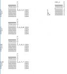
SerTxd ( "Key = ", #keyPress, CR, LF )
Pause 40
End If
Loop
ReadKeyPress:
dirsB = DIR_X
keyPress = MSK_X & pinsB ^ XOR_X
If keyPress <> 0 Then
dirsB = DIR_1
keyPress = MSK_1 & pinsB ^ XOR_1
If keyPress <> DIR_1 Then : Return : End If
dirsB = DIR_2
keyPress = MSK_2 & pinsB ^ XOR_2
If keyPress <> DIR_2 Then : Return : End If
dirsB = DIR_3
keyPress = MSK_3 & pinsB ^ XOR_3
If keyPress <> DIR_3 Then : Return : End If
dirsB = DIR_4
keyPress = MSK_4 & pinsB ^ XOR_4
If keyPress <> DIR_4 Then : Return : End If
End If
keyPress = 0
Return
Table %00000000, ( 0 )
Table %00000101, ( 1 )
Table %00000110, ( 2 )
Table %00000111, ( 17 )
Table %01000100, ( 3 )
Table %01000101, ( 18 )
Table %01000110, ( 19 )
Table %01000111, ( 20 )
Table %10000100, ( 4 )
Table %10000101, ( 21 )
Table %10000110, ( 22 )
Table %10000111, ( 23 )
Table %11000100, ( 24 )
Table %11000101, ( 25 )
Table %11000110, ( 26 )
Table %11000111, ( 27 )
Table %00001001, ( 5 )
Table %00001010, ( 6 )
Table %00001011, ( 28 )
Table %01001000, ( 7 )
Table %01001001, ( 29 )
Table %01001010, ( 30 )
Table %01001011, ( 31 )
Table %10001000, ( 8 )
Table %10001001, ( 32 )
Table %10001010, ( 33 )
Table %10001011, ( 34 )
Table %11001000, ( 35 )
Table %11001001, ( 36 )
Table %11001010, ( 37 )
Table %11001011, ( 38 )
Table %00010001, ( 9 )
Table %00010010, ( 10 )
Table %00010011, ( 39 )
Table %01010000, ( 11 )
Table %01010001, ( 40 )
Table %01010010, ( 41 )
Table %01010011, ( 42 )
Table %10010000, ( 12 )
Table %10010001, ( 43 )
Table %10010010, ( 44 )
Table %10010011, ( 45 )
Table %11010000, ( 46 )
Table %11010001, ( 47 )
Table %11010010, ( 48 )
Table %11010011, ( 49 )
Table %00100001, ( 13 )
Table %00100010, ( 14 )
Table %00100011, ( 50 )
Table %01100000, ( 15 )
Table %01100001, ( 51 )
Table %01100010, ( 52 )
Table %01100011, ( 53 )
Table %10100000, ( 16 )
Table %10100001, ( 54 )
Table %10100010, ( 55 )
Table %10100011, ( 56 )
Table %11100000, ( 57 )
Table %11100001, ( 58 )
Table %11100010, ( 59 )
Table %11100011, ( 60 )Do you see anything inherently wrong with that concept?
I don't suppose I could use a 14M2?
It does not have enough pins on any ONE port, but I don't suppose you can split the operation across both ports on the 14M2?
Along the lines of rows on portB, columns on portC kind of thing?
I suspect NOT, as the codes I have seen for matrix decoding, seem to rely heavily on being able to read the state of the whole port in one command as an important step in the code.
...but then, I often misunderstand things...