Hi All,
I have been working on a display for a lambda sensor to connect to the serial data output from a Tech Edge lambda controller see http://wbo2.com/.
I have a 2J1 model (http://wbo2.com/2j/2j1.htm), the serial data format is common to a number of the different models, the serial data format is explained here http://wbo2.com/sw/logtech.htm (the 2J1 uses the 2.0 data frame format). I want to display lambda http://en.wikipedia.org/wiki/Air_Fuel_Ratio#Lambda so the only information in the data frame I am interested in is the two bytes of lambda16 (the relationship between lambda16 and lambda is explained here... http://wbo2.com/sw/lambda-16.htm)
I am using a 28X1 at 16Mhz to get to the 19200 baud rate of the Tech Edge output. I have a MAX202 for level conversion. The display consists of 3 off 7 segment displays, they are common anode with 3off ULN2803s to sink the LEDs. I am using 3 off CD4026Bs to drive the 7 segs. The PIC controls the decimal points via the 8th channel in the ULN2803s. I have used a LM317T to set the voltage for the 7 segs. The dps have resistors in series to half the voltage. The 28X1, MAX202 and the CD4026Bs are powered from a 7805.
The code is as follows:
It took me a while to get the HSERIN working using the two byte qualifier shown at the top of the Tech Edge data frame format. This evening I tried the version above with the two byte qualifier in binary and it works. Does this mean I can put $5AA5 or 23205 instead? Two byte qualifiers are not that clearly explained in the manual (I had an earlier version working with a single byte qualifier which used a logic statement to check for the second byte of the qualifier)
I opted for clocking each of the CD4026s separately rather than cascading so the display refreshes quickly. This was no issue on the 28X1 as there were pins to spare.
The displayed value for lambda can range from 0.50 to 200, to affect this the decimal point moves. I am thinking about changing the code to display .999 - .500 ie 3 significant figures rather than dropping to 2 significant figures below 1.00
Initially the display flickered due to it displaying 0 briefly on resetting the CD4026s, by setting Display Enable low before refreshing the display this has been eliminated. I had to add the 0.1 second pause to limit the refresh rate so the display can be read, without it the refresh rate is too high.
What I have shown above is the tidy version, I have a development version with various SERTXD commands for debugging and various counter bytes for checking the function of the program. Hopefully the comments included will be sufficient for you to follow what going on.
I would appreciate any suggestions for simplifying or improving the code or the hardware, this is my most complicated picaxe project to date by a fair margin. Any suggestions for added functionality? Now this is working I am wondering about a two line LCD display(16x2 would do) with the ability to select some of the other data from the Tech Edge serial data for the second display line. I think the way to do that would be to use an 18M2 to communicate with the Tech Edge (simplest way to run 19200 baud rate?) and LCD firmware chip, that sound about right?
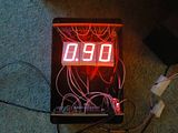
The box is too big but its one out of the scrap pile so will do for now.
At least its working") The next test is to put it on a vintage car to see if it can cope with the noise from the ignition system In the car it will run from a separate battery to the rest of the car. The car is 6volt electrics and the lambda sensor needs 12v for the heater coils. The data cable on the Tech Edge includes a battery voltage pin so I will run the display from that and connect the Tech Edge to the battery.
The next test is to put it on a vintage car to see if it can cope with the noise from the ignition system In the car it will run from a separate battery to the rest of the car. The car is 6volt electrics and the lambda sensor needs 12v for the heater coils. The data cable on the Tech Edge includes a battery voltage pin so I will run the display from that and connect the Tech Edge to the battery.
Regards
Rob
I have been working on a display for a lambda sensor to connect to the serial data output from a Tech Edge lambda controller see http://wbo2.com/.
I have a 2J1 model (http://wbo2.com/2j/2j1.htm), the serial data format is common to a number of the different models, the serial data format is explained here http://wbo2.com/sw/logtech.htm (the 2J1 uses the 2.0 data frame format). I want to display lambda http://en.wikipedia.org/wiki/Air_Fuel_Ratio#Lambda so the only information in the data frame I am interested in is the two bytes of lambda16 (the relationship between lambda16 and lambda is explained here... http://wbo2.com/sw/lambda-16.htm)
I am using a 28X1 at 16Mhz to get to the 19200 baud rate of the Tech Edge output. I have a MAX202 for level conversion. The display consists of 3 off 7 segment displays, they are common anode with 3off ULN2803s to sink the LEDs. I am using 3 off CD4026Bs to drive the 7 segs. The PIC controls the decimal points via the 8th channel in the ULN2803s. I have used a LM317T to set the voltage for the 7 segs. The dps have resistors in series to half the voltage. The 28X1, MAX202 and the CD4026Bs are powered from a 7805.
The code is as follows:
Code:
'PICAXE 28X1 with 16MHz resonator
'MAX202 Rx connected to IN7.  Tx unused
'3 off 7 segment displays with CD4026B drivers
'CD4026B
	'RST common.
	'CLOCKS are driven from separate PIC outputs, the CD4026Bs are not cascaded.
	'CLOCK INHIBITS common.
	'DISPLAY ENABLE daisy chained using DISPLAY ENABLE OUT pins
		'DP0		0
		'DP1		1
		'DP2		2
		'CLKUNI		3
		'CLKTEN		4
		'CLKHUN		5
		'RST		6
		'CLKINHIB	7
		'DISENB	PWM1/portc 1

	'To test the program copy and paste "23205,0,0,0,X,Y" into HSERIN dialogue box
	'subsitute X,Y for the MSB and LSB of Lambda16
	'significant lambda values in following table but all values 255,255 to 0,0 accepted
	'lambda	X	Y
	'228	 	255	255
	'100		191	128
	'5		141	0
	'4.5		128	0
	'1.5		32	0

setfreq em16				'external 16MHz resonator required to operate 19200 baud rate
hsersetup B19200_16,%01000 'for 28X1
symbol uni = b27
symbol ten = b26
symbol hun = b25
symbol dp = b24
symbol l16 = w0

startupscreen:				'light all the segments and decimal points to check display functions
	high 0,1,2				'light dps first
	pause 8000
	let uni = 8
	let ten = 8
	let hun = 8
	low 7					'CLKINHIB OFF
	pulsout 6,10			'RST
	gosub unt
	gosub tns
	gosub hns
	high 7				'CLKINHIB
	high portc 1			'this is the CD4026B display enable, it may be possible to PWM this pin to change display brightness

	for b0 = 1 to 2				'DISABLE THIS PAUSE WHEN RUNNING SIMULATION!
	pause 40000				'1000= 1sec at 4MHz at 16Mhz = 0.25sec. At 16MHz this is 10sec looped 2 times to
                                                        'allow lambda sensor to warm up.
	next b0

	gosub blank				'The display will show 0.0.0. until the first data packet is received from the tech edge

main:
	hserin [4000,timeout],0,5,(%0101101010100101)
	get 4,b0
	get 3,b1
	if l16>49023 then goto hundreds
	if l16>37503 then goto tens
	if l16>36863 then goto units
	goto subfive

hundreds:
	let dp = 0				'set decimal point position
		let w1 = l16 / 128	'this and the next line convert to decimal lambda
		let b4 = w1 - 283
		let b10 = b4/10		'drop units
		let b11 = b4/100		'drop tens
	let uni = b4//10			'using //10 can only return a value 0-9
	let ten = b10//10
	let hun = b11//10
	goto display

tens:
	let dp = 1				'set decimal point position
		let w1 = l16 / 128	'this and the next line convert to decimal lambda
		let b4 = w1 - 283
		let b5 = l16//128		'get remainder
		let w3 = b5*10		'multiply to get relevant significant figures
		let b11 = b4/10		'drop tens
	let uni = w3/128			'convert significant figures to decimal lambda
	let ten = b4//10
	let hun = b11//10
	goto display

units:
	let dp = 2				'set decimal point position
		let w1 = l16 / 128	'this and the next line convert to decimal lambda
		let b4 = w1 - 283
		let b5 = l16//128		'get remainder
		let w3 = b5*100		'multiply to get relevant significant figures
		let b10 = w3/128		'convert significant figures to decimal lambda
		let b11 = b10/10		'drop units
	let uni = b10//10
	let ten = b11//10
	let hun = b4//10
	goto display

subfive:
	let dp = 2				'set decimal point position
		let w1 = l16/16		'discard lsb only need lambda to 0.01
		let b4 = w1/512		'convert to decimal lambda
		let w3 = w1//512		'get remainder
		let w8 = w3*100		'multiply to get relevant significant figures
		let b10 = w8/512		'convert significant figures to decimal lambda
		let b11 = b10+50		'add offset
		let b12 = b11/10		'drop units
		let b13 = b11/100
		let b14 = b4+b13		'in case offset causes tens to spill to hundreds,
                                                'this should not happen as 5.00 is dealt with by units
	let uni = b11//10
	let ten = b12//10
	let hun = b14//10
	goto display

display:
	low 0,1,2				'Cancel previous DP
	high dp				'set new DP
	low 7					'CLKINHIB OFF
	low portc 1				'low display enable turning on and off stops visible
                                                'flicker of unused segments when digit doesnt change
	pulsout 6,10			'RST
	gosub unt
	gosub tns
	gosub hns
	high portc 1			'high display enable
	high 7				'CLKINHIB
	let b20 = 0				'HSERIN has received data so zero timeout counter
	pause 400				'this pause is to limit the refresh rate, its too fast without this!
	goto main

timeout:
	let b20 = b20+1			'timeout counter
	if b20 > 2 then gosub blank	'if timeout occurs 3 times in a row then the screen blanks,
                                                'until screen blanks it displays last value.
	goto main

blank:
	low 7					'display shows zeros and all dps, signals end of startup pause and timeout.
	pulsout 6,10			'RST
	high 0,1,2
	high 7
	return

unt:
	if uni = 0 then return endif
	for b15 = 1 to uni		'CLKUNI
	pulsout 3,10
	next b15
	return

tns:
	if ten = 0 then return endif
	for b15 = 1 to ten		'CLKTEN
	pulsout 4,10
	next b15
	return

hns:
	if hun = 0 then return endif
	for b15 = 1 to hun		'CLKHUN
	pulsout 5,10
	next b15
returnI opted for clocking each of the CD4026s separately rather than cascading so the display refreshes quickly. This was no issue on the 28X1 as there were pins to spare.
The displayed value for lambda can range from 0.50 to 200, to affect this the decimal point moves. I am thinking about changing the code to display .999 - .500 ie 3 significant figures rather than dropping to 2 significant figures below 1.00
Initially the display flickered due to it displaying 0 briefly on resetting the CD4026s, by setting Display Enable low before refreshing the display this has been eliminated. I had to add the 0.1 second pause to limit the refresh rate so the display can be read, without it the refresh rate is too high.
What I have shown above is the tidy version, I have a development version with various SERTXD commands for debugging and various counter bytes for checking the function of the program. Hopefully the comments included will be sufficient for you to follow what going on.
I would appreciate any suggestions for simplifying or improving the code or the hardware, this is my most complicated picaxe project to date by a fair margin. Any suggestions for added functionality? Now this is working I am wondering about a two line LCD display(16x2 would do) with the ability to select some of the other data from the Tech Edge serial data for the second display line. I think the way to do that would be to use an 18M2 to communicate with the Tech Edge (simplest way to run 19200 baud rate?) and LCD firmware chip, that sound about right?

The box is too big but its one out of the scrap pile so will do for now.
At least its working
The next test is to put it on a vintage car to see if it can cope with the noise from the ignition system In the car it will run from a separate battery to the rest of the car. The car is 6volt electrics and the lambda sensor needs 12v for the heater coils. The data cable on the Tech Edge includes a battery voltage pin so I will run the display from that and connect the Tech Edge to the battery.Regards
Rob
Attachments
-
180.3 KB Views: 38
Last edited: