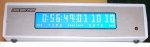
Project Box 4x40 LCD
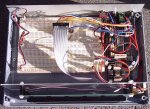
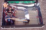
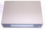
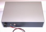
This project box is for semi permanent projects that require housing. It is equipped with AXE022 proto-board, AXE111 data logger memory expander, breadboard area, 40x4 LCD, DS1307 RTC module & infrared PCB.
Using an infrared remote controller negates the need to cut holes in the box for push buttons. Interaction with the Picaxe program is easily achieved by using a 08M2 to monitor irin then passing this incoming data on to the 40X2 master Picaxe via Hserout/Hserin scratchpad background receive. Interrupt on Hserflag, this method doesn’t require timeouts.
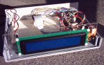
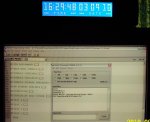
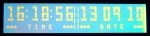
Currently this project box is running a version of my Large Digit Clock program, with the addition of displaying the date in large format.
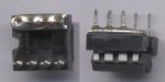
When using AXE022 proto-board with AXE111 data logger memory expander there is an address conflict for EEPROM. The AXE022 EEPROM is at address 001, which can be re-addressed as 000 with a clever trick. This requires two turned machined IC sockets one soldered to the AXE022 proto-board the other IC socket has pin one leg snipped off about half way and filed flat. Then bend a short length of wire into a U shape and solder to pin legs one through four. Now drill a hole through pin one all the way. The drilled hole is to allow the EEPROM leg to seat correctly without bending on insertion; this is done because during this process the hole will become deformed and shorter in length. Now insert the EEPROM into the IC socket and place the assembly into AXE022 proto-board EEPROM socket making sure that there is an air gap between the two IC sockets at pin one location.
This project box is for semi permanent projects that require housing. It is equipped with AXE022 proto-board, AXE111 data logger memory expander, breadboard area, 40x4 LCD, DS1307 RTC module & infrared PCB.
Using an infrared remote controller negates the need to cut holes in the box for push buttons. Interaction with the Picaxe program is easily achieved by using a 08M2 to monitor irin then passing this incoming data on to the 40X2 master Picaxe via Hserout/Hserin scratchpad background receive. Interrupt on Hserflag, this method doesn’t require timeouts.
Currently this project box is running a version of my Large Digit Clock program, with the addition of displaying the date in large format.
When using AXE022 proto-board with AXE111 data logger memory expander there is an address conflict for EEPROM. The AXE022 EEPROM is at address 001, which can be re-addressed as 000 with a clever trick. This requires two turned machined IC sockets one soldered to the AXE022 proto-board the other IC socket has pin one leg snipped off about half way and filed flat. Then bend a short length of wire into a U shape and solder to pin legs one through four. Now drill a hole through pin one all the way. The drilled hole is to allow the EEPROM leg to seat correctly without bending on insertion; this is done because during this process the hole will become deformed and shorter in length. Now insert the EEPROM into the IC socket and place the assembly into AXE022 proto-board EEPROM socket making sure that there is an air gap between the two IC sockets at pin one location.
Attachments
-
 7.5 KB Views: 172
 -
 22.4 KB Views: 238
Last edited: