PSX / PSone controller input to PICAXE

hippy

Technical Support
Staff member
Today's find at the car boot sale was a cheap PSX / PSone digital controller so today's gift to the community is how to interface that to a PICAXE. I used a PICAXE-20X2 but could be done with any others. Note the DAT line needs a pull-up if internal pull-ups aren't used ( no idea what value, try 10K ) . I simply ignored the ACK line.

Should be possible to convert the code to HSPI use but would need some 'SFR peeking' trickery as the controller returns data whilst sending, though one could simply ignore the data for those cases and assume the correct controller is attached. Should also be possible to read other controller's data but as I don't have any I can't test that.

Easiest way to get a suitable connector to plug into is to unsolder one from a broken PSone. I had one lying around and that allows two controllers and two memory cards to be attached - each needs its own ATT signal from the PICAXE.

If I can find a PSone memory card I'll give that a try.
 

Attachments

dannydig

New Member
Hi (from Australia!), thanks for posting this. I would love to interface a Playstation controller to one of my projects, but do not have much idea about how "bit-banging" works, although I have a basic understanding of how the Psx controller works (in terms of interfacing signals). I just want to use the analogue joysticks to control the two PWM outputs on my 28X1. Or for trial, just the digital buttons will do. The PICAXE manual's explanation of the shiftin/shiftout are still a bit too complex for me to understand.

I bought a wireless Psx controller off eBay (with analogue joysticks), and it works well with my old Playstation 1, however, I can't get it to communicate with the PICAXE 28X1 (internal osc), or 14M (not enough memory in chip). I have taken the code from http://users.tpg.com.au/gcrice/ps1_controller_interface.html, and the text file you have attached, and modified it slightly to match the different pin configuration, however, I keep on getting the message that "no controller attached" in your program, and an ID of 255 with the code from the users.tpg site (once again, most likely because of a lack of proper communication between the PICAXE and the Psx controller - the data is not being read properly - the line is pulled high with a 4k7 (not 10k) resistor, as you have suggested). I am not sure if it is something to do with timing.

I have tried with both 3.3V and 5V, and confirm that the Psx controller Rx/Tx circuit is working as it should (there is a signal Rx confirmation LED).

Could you please comment your code more (I understand the basic commands)? I am especially interested to learn what "CMD = bit0" and "b0 = DAT * $100 | b0 / 2" means, and why it is there.

Could the code required to read a Psx controller be compacted more to fit on a smaller device, such as the 14M, or 20M? I presume with the analogue values, data will have to be read into five byte variables altogether.

Otherwise, if I still can't get it to work, I will use an 18X/20X2 instead.

I have also found this page to be a good resource: http://www.curiousinventor.com/guides/ps2

Thanks for any help in advance. I will let you know if I get it working soon, and post how I did it.
 

hippy

Technical Support
Staff member
It should be possible to modify the code to use an analogue controller, even a wireless one. I'm not sure exactly what needs to change but should be straight forward. Unfortunately I don't have one to try.

The code I published can be trimmed to below 70 bytes so should fit in any PICAXE with a reasonable amount of program space to spare.

Reading 255 as an ID ( no controller attached ) suggests some circuit issue in moving from 20X2 to another PICAXE. You may have to supply other voltages to the wireless interface which are not required nor shown in the normal digital controller connections.

The "CMD = bit0" is used to set an output pin to the value of bit0 of variable 'b0', the byte used to send commands out.

The "b0 = DAT * $100 | b0 / 2" moves the 'b0' to the right to get the next bit0 to send while moving what is being returned by the controller into 'b0' from the lft. After the routine finishes, what was in 'b0' will have been sent, what was received is placed in 'b0'.

I'll look at adding more comments to the code but this was a personal project rather than official Rev-Ed code so it tends to follow the, "this works, use or figure out why if interested", approach rather than a tutorial on PSX interfacing. Just documenting what there is can be far more and take much longer than the code itself and it's often difficult to describe how to use the code with another PICAXE. I'll see what I can do.
 

henryarnold

New Member
Same Problem

I'm having the same problem with a PICAXE 28x2 and a wireless PS2 controller. I get no controller found. I have a logic analyzer and the data is always high. I've tried it with two different brands of wireless controllers and tested my controllers on a PS2 game console (at the store where I bought the controller) My first controller came from Lynxmotion and they claim that you don't have to hook up the 7.5-9V. I also haven't found anyone that says that ACK has to be pulled high. I was thinking of trying that.

Command is on the falling edge of CLK. Is data back before or after the rising edge of CLK? Your code reads the data BEFORE the clock goes high. I tired moving the read to right after the CLK goes back high with no luck. This looks simple to me but it just won't work!
 

dannydig

New Member
I also did try the 14M code above, however, may have found why it does not work with our controllers - see below:

I also have an Arduino board, and by following the information at the link below, I was able to interface my controller to control two PWM outputs independently with the Y-axis of each joystick.
http://pspunch.com/pd/article/arduino_lib_gpsx_en.html
(However, there was a issue which I am still trying to sort out, see below.)

Note that he states on his site "Currently, all timings are designed to work only on PS2 controllers. PS1 controllers are designed to run at half the clock speed which I haven't adjusted to yet."

This means that if hippy's code above is only designed to work with PSOne controllers, it may not work with the wired/wireless PS2 controllers we have (as they run twice as fast - perhaps by default) - unless a further additions to the code are made. But I have a feeling it may not be possible to read the PS2 signals with the low-end PICAXEs, as they run too slow (however, I have not confirmed this).

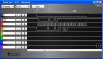
I monitored the clock and data lines on my analogue CRO (could not get a digital one to trigger correctly!) to confirm that the signal I was getting was clean - and it was (data lines where perfect and in sync with the clock - just thinking about it, that confirms that the Arduino was giving accurate clock pulses! I now know where the trouble may be).

Unfortunately, I do not have a PSOne controller to compare the signal against. However, my PS2 wireless controller should work on a PSOne unit, but I am not sure if the clock speed is automatically lowered when this happens. I thought both units would have had the same signal, however, the PS2 can measure button pressure as well, and possibly has more accurate joysticks (from what I read on Wikipedia - which also states they are backwards compatible).

Also note how much more complex the (Arduino library) code is! But it 99% works for me (on some controllers, it may work 100%. Mine was from a (eBay) store in Hong Kong).

Anyway, I think in the end, I will just put a PICAXE 08M in the controller connected to the joystick, and interface that to a wireless Tx module, to send to another PICAXE controlling PWM for a motor. However, I will experiment a bit more with the Arduino before taking things apart.

I will try to get hold of an old PSOne controller and check the signals, when time permits, and post back about my results. Perhaps it would be easier if I was to take a picture of the CRO screen, post it here, and get hippy to confirm it is the same. I will see if I can do that within the next few days.

But for $14 AUD, the controller was good value any way - two joysticks (worth $4.50 AUD each from Little Bird, two motors, and possibly a multi-channel transceiver). I can use the joysticks in many other places.

Hopefully someone will work this out one day - however, I am not sure if it is possible with 4/8MHz parts, because the timings have to be accurate to milli (or nano) seconds.

----------------------------------------------------------------------------------------
----------------------------------------------------------------------------------------

Below is the conversation I had with the author of the Arduino (http://arduino.cc and http://arduino.cc/en/Main/ArduinoBoardDuemilanove) library (running at 16MHz):

The first email is at the bottom. Start from there.

----------------------------------------------------------------------------------------
If you look at the end of GPSX.c, you will find two functions,
"psx_cmd" and "psx_read_write_byte".

psx_cmd sends the commands to the controller.
psx_read_write_byte is called from psx_cmd to read one byte of response
from the controller at a time.
--------------
You may know much more about micro processors than me so this may be
redundant...

What goes on is that the controller receives a "clock" signal from the
Arduino which is represented in a form of one of the pins alternating
between high and low.

That is the primary reason you see a series of commands in the following
order.

1. digitalWrite(CLK_PIN, LOW) <-- Generate a clock signal for the
2. digitalWrite(CLK_PIN, HIGH) <-- controller to send the next bit
3. digitalRead(DAT_PIN) <-- Read the bit output from the controller
--------------
Between the two digitalWrite and digitalRead, you will see

delayMicroseconds( clk_half_cycle[psx_type] );

If you open GPSX.c and search for keyword "delayMicroseconds", you will
find other locations where waits are used to adjust timings and waits.

To answer your question on using decimal points rather than whole
numbers, whether it is valid or not depends on what documents on
delayMicroseconds say.

Also note that the wait time is not accurate (usually longer than what
you specify) as there is over head to calling the functions.

I hope this is of some use.

> Hi,
>
> Thanks for your reply.
>
> I used a CRO to check the signal from the wireless receiver, and it is
> fine - when the left joystick is pushed up, it stays constant in value.
>
> However, I think as the Y-axis signal for the left joystick is the last
> one sent, the program in the Arduino may be getting tricked on the last
> clock signal - it is just a matter of nano/milliseconds I think.
>
> You are correct that the best thing to do is to try another controller.
> I did try adjusting the timings, however, this made this worse - the
> joysticks would not respond at all. Can you put number like "1.5" in
> these fields, or whole numbers only? Also, what exactly to these numbers
> control?
>
> From Danny
>-----------------------------------------------------------------------
> > Date: Fri, 26 Mar 2010 13:35:39 +0900
> > From:
> > To:
> > Subject: Re: PS2 Interface For Arduino - Question
> >
> > Hi Danny,
> >
> > It is always a pleasure to know there are ones making use of my work.
> >
> > Unfortunately, I do not have a straight forward answer for you, but I
> > have some hints.
> >
> > The library has some adjustable figures regarding synchronization
> > timings. Default settings were chosen from trial & error rather than
> > measurement. In the process of setting these figures, I've found some
> > controllers returning incorrect values only for specific keys, rather
> > than malfunctioning or not responding at all... this sounds like your
> case.
> > Although I've also suspected noise in the power supply at one point,
> > after all the debugging I have concluded that some controllers are
> > simply more timing critical than others... after all, there are designed
> > only to run perfectly on a hardware with specific specs.
> >
> > I have two things in mind you may want to try.

> > 1)
> > The communication timing can be adjusted by the following line.
> >
> > -- GPSX.c, line 29.
> >
> > static unsigned char clk_half_cycle[] = { 2, 1}; // nsec
> >
> > The values now set to 2 and 1, can be replaced with any figure between 0
> > to 5, or perhaps higher.
> >
> > 2)
> > Simply try another controller.
> >
> > As mentioned, I have a controller (non Sony) which, while works fine on
> > my PS2 up till today, never gave me the desired stability with my
> library.
> >
> > This may be an easier way out.
> >
> > Good luck with your project, and please feel free to share any further
> > discoveries.
> >-----------------------------------------------------------------------
> > > Hi,
> > >
> > > I am using the library on your website (GPSX), to control PWM to two
> > > LEDs, depending on the Y state of the joysticks on my wireless PS2
> > > controller.
> > >
> > > My code is working as expected, however, when I push the left joystick
> > > right up to its top position, rather than outputing a constant value of
> > > 0, it outputs a random value every few seconds (between 0 and 255),
> > > causing the LED to blink randomly depending on the value read (it
> should
> > > stay off at this position). Are you aware of any bugs/issues with your
> > > library? The right joystick is working fine with both X and Y
> positions.
> > > The left joystick is working fine sensing X positions, and the lower Y
> > > range is sensing fine - the problem only occurs at the topmost Y
> > > position. The device I am using is not an official Sony controller,
> just
> > > something I got from eBay. It works with my PS2 well.
> > >
> > > I will attach it to a CRO tomorrow, to see what's going on. I have
> clean
> > > power supply lines, and the board is working as expected - I am using
> > > the Arduino Duemilanove.
> > >
> > > The digital input buttons are all working too.
> > > _
> > > Below is my code:_
> > >
> > > #include <math.h> //if I don't include this, I get a compile error
> > > #include <GPSXClass.h>
> > >
> > > int ledPin = 9;
> > > int ledPin2 = 10;
> > >
> > > void setup()
> > > {
> > > PSX.mode(PSX_PAD1, MODE_ANALOG, MODE_LOCK);
> > > PSX.motorEnable(PSX_PAD1, MOTOR1_ENABLE, MOTOR2_ENABLE);
> > > }
> > >
> > > void loop()
> > > {
> > > PSX.updateState(PSX_PAD1);
> > > analogWrite(ledPin,ANALOG_LEFT_Y(PSX_PAD1));
> > > delay(50);
> > > PSX.updateState(PSX_PAD1);
> > > analogWrite(ledPin2,ANALOG_RIGHT_Y(PSX_PAD1));
> > > delay(50);
> > > }
> > >
> > > Thanks for providing the library; it is the best one I have used so
> far.
> > > From Danny
 

henryarnold

New Member
Wireless PS2 - No Go

Thanks for the post. I've read many net postings on interfacing to the PS2 controller. Has anybody seen any timing specs on the ATT, SCLK, DATA, and CMD signals? I haven't. Are there critical clock pulse width, cmd setup and data hold timings? I assumed since it wasn't mentioned that the PICAXE and other Basic chips are slow enough that there was no issue. I hadn't considered that being too slow, the PICAXE could not read data back at all. I used a logic analyzer on my setup. I see the ATT go low, the CMD is presented and the CLK goes low. I do not see any data arriving on the logic analyzer so this is not a simple matter of the PICAXE not reading the data quick enough. The logic analyzer is 100 MHz so it would see the data. I'm thinking that there's some magic relationship between when the ATT goes low and the first CMD is presented. My next move is to buy a used PS2 Console and reverse Engineer it.

Has anyone made a PICAXE work with a wireless PS2 Controller?
 

hippy

Technical Support
Staff member
It could be that some controllers have tighter timing requirements than others, that the controller is looking for a particular input within a particular time frame. I don't know if this helps at all but this is what I'm seeing with my button pad when run on a 20X2, bit-banged at 8MHz ...
 

Attachments

henryarnold

New Member
PICAXE is Too Slow For PS2 Controller

I solved the problem. With my original program I was clocking the PS2 controller at about a period of 5ms (200 Hz). I changed to a C.5=0 and C.5=1 style bit bang with no loops and I got the timing down to 1.2ms period on the clock. I now get data but as soon as I try and read the input data, the period goes to 1.6ms and it fails. Evidently, the controller has a minimum clock frequency of around 1-1.2 ms above which it stops working. My indication that there is an error is that my controller receiver has a green and red light. When I connect, they are both on. When I start trying to talk to the the receiver, I get a flashing red light. When the guy at the store rechecked my controller with a PS2 console, both the red and green lights were steady on.

Conclusion: I will need a faster processor to communicate with the PS2 controller. I suspect that even a 1 ms clock period is too slow. I probably should be closer to 10-100 us which the PICAXE obviously can't do.
 

henryarnold

New Member
Update: I downloaded the latest manual and found out about the hspiin and hspiout commands. I successfully implemented the hspiin and hspiout SPI commands which clock more than fast enough for the PS2 controller. The only issue had to deal with is that the hspiout command only does MSB first. I flipped the command bytes and all is working now. Here's the basic code for a PS2 Wireless Controller. I Only tested it with the 28X2. Be sure to hook up your SPI to the correct hardware pins which are 14=sclk, 15=sinput(DATA), 16=soutput(CMD) on the 28X2. I used B.0 for ATT. This example does not have the joysticks enabled. See all of the websites that show you the command sequence to enable the different modes like joysticks.


==============================================
#picaxe 28x2
#Terminal 9600

Symbol ATT = B.0 ' Attention Output

high ATT

hspisetup spimode10e, spimedium 'setup - cmd is msb first
do_it:
low ATT
hspiout($80, $42) 'basic query 80 is 01 flipped, 42 is 42 flipped
hspiin (b7,b0,b1)
high ATT
pause 50
if b7 <> $5A then do_it '5A is end of header, must be present
if w0 = $FFFF then do_it 'w0 is b0 + b1 = FFFF no buttons pressed
w0 = w0 ^ $FFFF 'invert bits

If bit15 = 1 Then : SerTxd( "Left2 " ) : End If
If bit14 = 1 Then : SerTxd( "Right2 " ) : End If
If bit13 = 1 Then : SerTxd( "Leftt1 " ) : End If
If bit12 = 1 Then : SerTxd( "Right1 " ) : End If
If bit11 = 1 Then : SerTxd( "Triangle " ) : End If
If bit10 = 1 Then : SerTxd( "Circle " ) : End If
If bit9 = 1 Then : SerTxd( "Cross " ) : End If
If bit8 = 1 Then : SerTxd( "Square " ) : End If
If bit7 = 1 Then : SerTxd( "Select " ) : End If
If bit6 = 1 Then : SerTxd( "? " ) : End If
If bit5 = 1 Then : SerTxd( "? " ) : End If
If bit4 = 1 Then : SerTxd( "Start " ) : End If
If bit3 = 1 Then : SerTxd( "Up " ) : End If
If bit2 = 1 Then : SerTxd( "Right " ) : End If
If bit1 = 1 Then : SerTxd( "Down " ) : End If
If bit0 = 1 Then : SerTxd( "Left " ) : End If
SerTxd( CR, LF )
goto do_it
 

dannydig

New Member
Hi henryarnold,

That is much simpler than I thought! I think using hspi is the way to go. If only it was available on a PICAXE 14M, however, I also have a 28X1 I can use.

I have a rough idea of how to set the modes and get the analogue joysticks working. I will let you know how I go.

Could you tell me what the following codes do/how they work?:
hspiout($80, $42) (why have you stated $80 and $42?)
hspiin (b7,b0,b1)
if b7 <> $5A then do_it (what is $5A?)
w0 = w0 ^ $FFFF

At this point in time, I do not have any experience with using/configuring hspi on the PICAXE.

Thanks.
 
Last edited:

hippy

Technical Support
Staff member
I successfully implemented the hspiin and hspiout ... The only issue had to deal with is that the hspiout command only does MSB first.
I completely overlooked that when I couldn't get SPI to work and gave up on it ;-)

To get the response back to the request for data, so you can check the controller is the expected type, you should be able to use the "HSPIOUT( $80, $42 )" then immediately "PEEKSFR $C9, b0" to get the controller type into b0 ( reversed bits ). I haven't actually tried that.

Thanks for getting HSPI to work.
 

henryarnold

New Member
I'm glad to contribute. I got the analog mode working and have a nice example program that is only about 50 lines long. Where is the best place to post it? Is there a place on this site for example code?

I added the new code to my robot program and can now steer my robot using the PS2 controller. You can't beat $20 for an RF wireless controller with joysticks and a bunch of buttons. The PS2 also allows up to four controllers operating at the same time. I'm building a robot game which will include four robots on the playing field.

Hippy, you appear to work for Revolution. I also found a bug in the new shiftout command. Where should I report it? The shiftout documentation has a mistake in the mode description and settings (1,2,4,5). I suspect they meant (1,2,3,4) and the settings for clock idles high don't work. Mode setting 5 idles the clock high but doesn't output the data. I would have liked to use this command but I could not keep the clock high and get the data to come out.
 
Last edited:

henryarnold

New Member
I completely overlooked that when I couldn't get SPI to work and gave up on it ;-)

To get the response back to the request for data, so you can check the controller is the expected type, you should be able to use the "HSPIOUT( $80, $42 )" then immediately "PEEKSFR $C9, b0" to get the controller type into b0 ( reversed bits ). I haven't actually tried that.

Thanks for getting HSPI to work.
$80 and $42 are flipped versions of $01 and $42 which are the normal PS2 headers. $42 flipped is $42 and $5A flipped is $5A which makes it confusing when looking at what I send and receive versus what other programmers send which are using LSB first. $5A is the third byte back from the controller. I check that I get this byte to make sure I'm not getting a bad message. I should also being checking the ACK signal. Someone can try that and see how important it is. I neglected this signal on my PCB design so for now I'm stuck with no easy way to read it. Most of the examples also ignore it.

I finished the analog mode for the SP2 and will post it possibly in this message string. I don't bother flipping the reversed answer bytes except for the joystick settings which are easier to use if in the correct format.
 
Last edited:

hippy

Technical Support
Staff member
Hippy, you appear to work for Revolution. I also found a bug in the new shiftout command. Where should I report it? The shiftout documentation has a mistake in the mode description and settings (1,2,4,5).
You're correct, I am employed by Rev-Ed having previously been an avid PICAXE hobbyist. I've made a note of the suspected bug and we will look into that. I've never been clear on which mode is which or what they are each meant to do.
 

henryarnold

New Member
Sony Playstation PS2 Controller SW for PICAXE 28X2

Thanks for all the suggestions and help. Here's the final Sony PS2 Controller code for the 28X2. This reads both joysticks and all buttons including the little known down push on the joystick handles.
 

Attachments

dannydig

New Member
hippy/henryarnold, thanks very much for all your work so far.

I have tried converting henryarnold's code to work on the 28X1. However, I am getting no results showing up in the terminal, but the mode LED (on the controller) is coming on.

I have wired it up the same way as you have shown (with the 28X2). Can you see any problems with the (modified) code below?

Also, could you tell me what "red mode" and "green mode" mean in regards to a Playstation controller?

I got my controller from the following eBay listing - only $14 AUD and free shipping!
http://cgi.ebay.com.au/New-PS2-Wireless-Game-Controller-for-Sony-Playstation-2_W0QQitemZ250586248643QQcmdZViewItemQQptZAU_Video_Game_Accessories?hash=item3a581ab5c3

Of course, I chose the clear case, so I could see the parts inside!

----------------------------------------------------------------------------------

'(Note that parts of the code have been commented out)

#picaxe 28x1
#no_table
#com 1
#Terminal 9600

'Symbol DAT = 4 'Input with pull-up (not required)
'Symbol CMD = 5 'Output (not required)
'Symbol CLK = 3 'Output (not required)
Symbol ATT = 0 'Output

'===============MAIN part of the program==============================
We_Start_Here:

'dirsB = %00000001 ' B.0 is output (command does not work with 28X1)

high ATT
hspisetup spimode10e, spimedium 'added "hspisetup" in front
goto Analog_Mode

Digital_Read: 'basic digital query
low ATT 'ATT =attention must go low during transaction
hspiout($80, $42) 'output the header bytes $01 and $42 flipped is $80 & $42
hspiin (b7,b0,b1) ' input three bytes of data. b7 should be $5A
high ATT 'flipped is also $5A
pause 50
if b7 <> $5A then Digital_Read
if w0 = $FFFF then Digital_Read
gosub display_button_results
goto Digital_Read

Analog_Mode:
gosub Analog_Enable
Analog_Read:
low ATT
hspiout($80, $42) 'analog query
hspiin (b7,b0,b1,b2,b3,b4,b5) 'analog mode has 7 bytes, last four are joysticks
high ATT
pause 50
if b7 <> $5A then Analog_Read
if w0 = $FFFF then joystick
gosub display_button_results
joystick:
b2 = b2 REV 8 'reverse the order of bits to make MSB first LSB first
b3 = b3 REV 8 'because SPI hardware does MSB first, this corrects bit order
b4 = b4 REV 8 'I did not do this for buttons
b5 = b5 REV 8
if b2 <> 128 Then : SerTxd("Right JSTK L/R ", #B2, CR,LF) : End If
if b3 <> 128 Then : SerTxd("Right JSTK U/D ", #B3, CR,LF) : End If
if b4 <> 128 Then : SerTxd("Leftt JSTK L/R ", #B4, CR,LF) : End If
if b5 <> 128 Then : SerTxd("Leftt JSTK U/D ", #B5, CR,LF) : End If
goto Analog_Read


'=======================subroutines=====================================
display_button_results:
w0 = w0 ^ $FFFF
If bit15 = 1 Then : SerTxd( "Left2 " ) : End If
If bit14 = 1 Then : SerTxd( "Right2 " ) : End If
If bit13 = 1 Then : SerTxd( "Leftt1 " ) : End If
If bit12 = 1 Then : SerTxd( "Right1 " ) : End If
If bit11 = 1 Then : SerTxd( "Triangle " ) : End If
If bit10 = 1 Then : SerTxd( "Circle " ) : End If
If bit9 = 1 Then : SerTxd( "Cross " ) : End If
If bit8 = 1 Then : SerTxd( "Square " ) : End If
If bit7 = 1 Then : SerTxd( "Select " ) : End If
If bit6 = 1 Then : SerTxd( "Left JSTK " ) : End If
If bit5 = 1 Then : SerTxd( "Right JSTK ") : End If
If bit4 = 1 Then : SerTxd( "Start " ) : End If
If bit3 = 1 Then : SerTxd( "Up " ) : End If
If bit2 = 1 Then : SerTxd( "Right " ) : End If
If bit1 = 1 Then : SerTxd( "Down " ) : End If
If bit0 = 1 Then : SerTxd( "Left " ) : End If
SerTxd( CR, LF )
return


Analog_Enable:
low ATT
hspiout($80,$C2,$0,$80,$0) 'enter config mode
high ATT

pause 1
low ATT
hspiout($80,$22,$0,$80,$C0,$0,$0,$0,$0) 'Set Mode to Analog
high ATT

low ATT
hspiout($80,$C2,$0,$0,$0,$0,$0,$0,$0) 'exit config mode
high ATT
pause 50
return
 

henryarnold

New Member
Dannydig,

My PS2 Controller also has a red and green light. Both lights come on when the controller is on and has found the hand held half of the controller. During debugging, I would get a flashing red light if the clocking was too slow or if there was an error in the message. I believe the flashing was a faster rate then the flashing red light you get when the hand held part is turned off. A slow flashing red light ligh occurs when the hand held part is off or has timed out.

I had a lot of trouble creating this software and the only reason I got it to work was that I was able to use a logic analyzer to see what was happening. The different modes change the polarity of the clock and where the clock edge changes in relation to the data. This is impossible to see without a scope or analyzer. PICAXE and even PIC documentation is not clear regarding this relationship. I've only tested my software with the 28X2 and one controller which came from Lynxmotion. Its possible that it won't work with other PS2 controllers.
I would focus on any command differences between 28X1 and 28X2. Try to borrow a 2 channel scope so you can examine what is going on.
 
Last edited:

henryarnold

New Member
Dannydig,

You should also try printing b7 and w0 to see if you are getting $5A and something like $FFFF. If not, you are not succesfully accessing the PS2 controller. My previous suggestion of using a 2 channel scope to see where the clock is in relation to the commands will help.

Henry Arnold
 

henryarnold

New Member
Guys,

I went out and bought another PS2 controller (Logitech) to try with my code. IT DOES NOT WORK. So the report of troubles from Dannydig are correct. The code I published has something wrong with it that it does not work with all controllers. This is actually good news because I can figure out what is wrong and fix it. I'll let you know what I come up with.

Henry Arnold
 

Lostmyed

New Member
Guys.
Has anyone had any luck getting any code to work with non-sony ps2 wireless controllers. All i can find on ebay or aywhere else actually are 3rd party ps2 (wireless) controllers! I have found officially licensed ones and i'm wondering if they will work ?
cheers !
 
Top