Capacitive water sensor

Tyro

Member
I nearly had a flood in my basement due to a small leak (corroded valve) becoming not so small when I was away for Christmas. I am now thinking about a low-level water sensor using the capacitance change from a dry to a wet state. When low levels of water are detected, a relay would open and switch my well pump off.

The sensor would be a thin printed circuit board with interdigited tracks. Every other one would be connected to each other to form a low value, flat capacitor. The track side would be coated a thin layer of epoxy to seal the electrical parts from moisture and corrosion. The PICAXE and components would allso be on this board to minimize connecting cable capacitance.

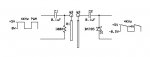
There are a number of different ways to measure a small capacitance using a PICAXE; generate a high(ish) frequency ac using the PWM function, rectify and measure the resulting current; drive both capacitor terminals to ground, (known starting condition) then drive one terminal high and immediately measure the voltage on the second terminal, the higher the voltage the greater the capacitance; make a relaxation oscillator like a 555 chip and measure the period.

Any other ideas on how to do it or experience with water sensing?
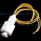
 

ToggyHead

New Member
In my attempt to detect and monitor water levels i found that nothing really work long enough as water corrode pretty much everything and when i tried what you are describing here i ended up with lots of other problems including a small build up of debris and mud which affected the measurements. I must add that living on a farm and relying mainly on stream water and rain water my tanks get probably more dirt than a normal city house get from scheme supply. Back few years ago i found this chip, not sure if still in production but worth having a look. I did play with it and found very interesting the results. I never ended up designing the final circuit but had it on a breadboard for few weeks. I should have more infos about it, let me know if you want me to find (read dig my crap to find it;) ) all the docs i have. If you need to detect a small amount of water at floor level it may be worth to play with a RH sensor at about 50mm from floor. In case of flood the sensor will pick up the increase in moisture. (this only works in enclosed environment and not in the open. Let me know if you get stuck. At the moment i have in my tanks a simple 2in pipe with a float in it. The float rise according to water level and once full it hit the cap where i mounted two big bolts. I feed 3Vac and detect the closure :eek:.
 

ingeer

New Member
I have been using a 40106 Schmitt trigger to detect/control the solution level in my flood-&-drain hydroponics system. The same probes have been in use for five years, triggering once an hour, every hour, for the past five years.

One input leg of the 40106 is biased to +5V by a 5megohm resistor, and the other leg is at 0V (earth) potential.

At high solution level the solution pulls the +5V input to earth.

No corrosion, reliable, and cheap. The probes are actually two thumb tacks (drawing pins) pushed through the side of one of the plastic growing trays.

Ingeer.
 

premelec

Senior Member
If you use contact electrodes use AC excitation or they polarize... I've seen a smoke detector chip used to detect very small leakage currents [like come from ionization chamber] and blow a horn.

A simpler method is an expanding sponge with a magnet on it to a Hall or reed switch. OR

A water soluble 'pill' which allows contacts to close when it gets wet and dissolves with suitable springs and coupling.

Both of these require some fiddling to work and may not work if you have high humidity rather than liquid water....
 

ToggyHead

New Member
That's what i was saying before, any DC used will work for very little time due to it..... and that is why i use 3Vac... :D
 

hippy

Ex-Staff (retired)
Don't know if it helps or how one would use it in a sensing application but with a PICAXE which supports HPWM it's possible to put a square wave out on one pin and the inverse on another, anything which is connected between those two pins will see an alternating current flow; a two-leg bi-colour LED plus R will have both LED's illuminated alternatively.
 

hippy

Ex-Staff (retired)
Good point - As the pin goes high and the cap charges current flows one way, then when the pin goes low and cap is discharging the current flows the other way. Quite simple really.

I'm wondeing if the voltage doubler interfaces to the I/O pins could be simplified or removed. I'll have to spend longer looking at your thread.
 

ToggyHead

New Member
hippy, yes that would work, as long as what is immersed in water is fed by ac you will never experience electrolysis. Any other voltage not swinging + to - will fail. By the way this just sparked a new thought in my head..... what about building a desulfator for batteries and having a positive peak followed by a negative one? In theory that would loosen up faster the particles that stuff up car batteries.... uhmmmm :rolleyes:
 

KMoffett

Senior Member
Good point - As the pin goes high and the cap charges current flows one way, then when the pin goes low and cap is discharging the current flows the other way. Quite simple really.

I'm wondeing if the voltage doubler interfaces to the I/O pins could be simplified or removed. I'll have to spend longer looking at your thread.
In an experiment I tried to minimize the circuit. To maintain the AC on both electrodes I needed to retain the capacitor in the input side. In order to not have the input pulled negative I retained one of the diodes. The program then has to deal with a 4KHz pulsing +5V input, rather than a DC level.

The pulse height, with 22 Ga. wires, is ~1V on contact with the water and 5v at ~ 1/4" submersion.

Ken
 

Attachments

Last edited:

nbw

Senior Member
I used 2 x stainless steel probes (made from TIG welding rods 1.6mm) for my saltwater fish tank. As folks will vouch, saltwater and DC electricity (mmmmmmmm). Using AC, and a probe wipe every month, they worked fine in my tank sump (lots of fish rubbish floating around in there). And if you want to get elegant and measure multiple levels, use different length probes. From memory I pulsed AC at about 5 kHz through the probes, and took loads of averages etc to work out salinity. Of course, if you just want to measure level, it shouldn't be too hard/////////
 

boriz

Senior Member
EEK! You electrocute your fish 5000 times a second?

When I was a kid, I accidentally killed my two goldfish (Rambo and God) while testing out my newly invented auto-fishtank-cleaner. Only 12v and no gap between conductors greater than 1cm. Both fish jumped and floated to the surface. Rambo died instantly, God a day later. I got over it.
 

nbw

Senior Member
haha :) nope, the probes were in the sump. The corals and fish were "upstairs" in the main tank. And I'd only sample for a few seconds every hour to check the salinity. Small voltages too, about 8VDC either side of 0V from memory.
 

Jeremy Leach

Senior Member
How about just making a small float attached to a microswitch? It's a sensible suggestion. Get a small block of polystyrene as a lightweight float, and get a sensitive microswitch and job done - perhaps?
 

acmeuk

New Member
Cheap Float Sensor

Hi Guys

For a simple, cheap and robust float sensor search on eBay for ' Float Liquid Sensor' and you should find items like the one shown in the attachment.

They cost about £1.50 each, post paid. The slight down side is that they are shipped from Hong Kong and take about 3 weeks to arrive.

I ordered 3 and was so pleased with them I ordered another 3.

Hope this helps someone.

Regards

BillP
 

Attachments

techElder

Well-known member
I must have missed this thread the first time around.

Heck, I've been using a wooden clothes pin, a wire pair (bare ends wrapped around the closed end of the clothes pin to form a switch, a 9V battery, a buzzer alarm in the house and an aspirin to keep the 'switch' contacts open in the absence of water.

The aspirin will deteriorate over time, but then you get to test the system. ;)
 

papaof2

Senior Member
Hi Guys

For a simple, cheap and robust float sensor search on eBay for ' Float Liquid Sensor' and you should find items like the one shown in the attachment.

They cost about £1.50 each, post paid. The slight down side is that they are shipped from Hong Kong and take about 3 weeks to arrive.

I ordered 3 and was so pleased with them I ordered another 3.

Hope this helps someone.

Regards

BillP
I've used a similar float switch as a blocked drain alarm for the drain on an ouside stairway to a basement. http://www.jecarter.us/picaxe/WaterLevel-08.html

It's been running at my daughter's house for several years and has warned of a blocked drain (thus preventing a flooded basement) at least twice - thus saving many times over what the parts cost. The Sonalert used for the alarm is loud enough and annoying enough to wake someone sleeping two floors above the alarm location. Annoying to be awakened at 2AM by a steady beep-beep-beep but better than finding water over the carpet a few hours later ;-)

John
 
Top