PCB Audio Traces

George Sephton

Senior Member
Hi All,
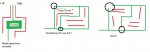
Im making a pcb that basically takes 7 audio inputs (3 phono, 3 jack and 1 ipod...in stereo) and with the use of the DS1805 and a decade counter and loads o' transistors selects one and outputs it with volume control. Most of the board uses 0.1 inch traces but is this alright for audio, what do I need to think about because I have an iPod dock at home (surprising because it was reasonably expensive) but when i plug my speakers into them they add a nice hum to my room, obviously I'd rather this didn't happen now I have more control over my stuff when I build it. Is 0.1 inch too small or do I need great thick .5 inch tracks or would that ruin, im kinda a noob :rolleyes: to resistance in terms of wiring and such.

Thanks for any help,
George S :p
 

Andrew Cowan

Senior Member
It's all about interference. Little current is carried, so track thickness is not that important. However, interference and sheilding are. You'll want a ground plane on the PCB to minimise interference.

A
 

jglenn

Senior Member
Right on Andrew. I would add:

1. only need thick traces for high currents. 15 mil is fine for signals.

2. ground plane is best, but understand why. Without one, you can improve signal integrity by reducing the LOOP AREA of the signal and return traces, they are always a pair. Run them next to one another, or shadow on the top and bott layers. Separating them makes a loop antenna, we see this in switching power supplies and EMI. It is called Transmission Line. Now you see why the ground plane is so good, it provides plenty of stray capacitive coupling to ground, literally sucking up noise. You are trying to make the pcb equivalent of a coax cable.

3. Keep the analog and digital separated, separate grounds and 5V, join only at
the power supply output cap.

4. Forget monster cables and gold plated everything. Waste of money.
Do use polyprop caps, if anyone knows of better ones please tell me! :cool:
 

moxhamj

New Member
All the above advice. Plus - if you are getting hum, sometimes that can be due to a ground loop. Say you have two audio boxes and you connect them with a stereo cable with 3 wires - Left, Right and Ground. That will work fine. But say you decide to connect the left signal with its own RCA cable, and the right one also with its own RCA cable. Now you have 4 wires - Left, Right and two Grounds. This creates a ground loop, where current can go round and round the ground in a circle. It might seem a strange solution but if that ever happens, cutting the ground on one of those RCA cables will solve the problem.

It won't be an issue with your board, but it might explain why your ipod hums. There are other reasons too, like poorly filtered power supplies, or even power supply transformers physically too close to audio lines. Sometimes you need to build the power supply in a seperate box. Or put it in a metal box. Or use a big box and have the power supply over in one corner and the audio 30cm away.

A switch box will be very handy. I've used rotary switches - eg 6 position two pole for left and right. Possibly simpler than electronic switching but a bit 'old skool'.
 

BeanieBots

Moderator
All the major points have been raised so I don't have any extra to add in that respect, but I would like to point out that this problem is not restricted to audio. With audio it is obvious when you have picked up such noise because you can hear it. With other sensors, it is not so obvious but just as easy to pick up. Beware.
 

Dippy

Moderator
Good points raised.
For line level signals 0.1" is easy enough, you could use far thinner.

I can't add to the points raised above but just add that neatness and common sense prevails.

Did you ever get o grips with a voltage regulator? Its not something creeping over from an error on that is it?

(Good point by BB. We see many issues of 'lousy ADC', but we forget how easy it is to make terrible analogue circuits. I'm sure we've all done it at some stage.)
 

QuIcK

Senior Member
I dont know how much you know about audio kit, so:

think about your ground plane carefully. between signal tracks, put an extension of the ground plane. this will shield them from each other and reduce crosstalk. Also, make sure that each "ground" bit has a direct link back to 1 point, dont make 2 different routes back if you can. ie dont make ground loops.
See attached (I cut the ground loop at the wrong part... the squiggle through the middle should have been 'cut' at the top. try to keep local grounds roughly the same length.)

If your looking at volume control, there is a PGA2310 by TI. its a stereo volume control, operated by SPI. extremely easy to bit bang. It also doesnt need DC blocking caps, or any other external circuitry. It may be worthwhile putting in dc blocking caps on the inputs, tho, just to make sure you arent biasing the PGA and removing headroom.

For signal select, I would suggest relays over jfet switches. they sound better. use a pic, use a BCD convertor to select relays, meaning you can get away with a smaller pic. put the PGA2310 just after the last relay, so you only need one of them.

some suggestions:
if your using a pic, you can use a remote control etc.
also, you can "level" match your inputs. so if you listen to your ipod on 1/2 volume thru headphones, you dont want to crank it up when you plug it into your hi-fi to get a decent signal level out of it. so you can either boost its volume with the PGA, or trim down the cd/computer etc. so all the levels going into the amplifier (out of the switcher) are the same.

If you are going to use op-amps/PGAs in your circuit:
think about your power supply carefully. calculate the power consumption, multiply it by 2 to make sure, then use 1000 uF per amp for smoothing/filter caps. DONT USE FIXED VOLTAGE REGS for you +/- rails. They are noisey! use variable voltage ones, read up on them!
run it from an AC-output "wallwart" style power supply, if you are not comfortable making your own mains psu. put that into a non-discrete diode rectifying bridge, with small non-biased caps between the terminals.
http://www.tnt-audio.com/clinica/ssps1_e.html has some good info for building a butch power supply. tone it back slightly, so its not over-kill.
The quietness of your signal path will stand & fall on the power supply.
oh, and do a seperate 5v reg from that to power your control & relays.
 

Attachments

Last edited:
Top