RGB Floodlight

Andrew Cowan

Senior Member
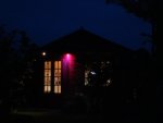
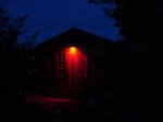
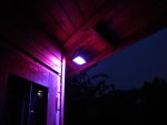
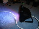
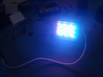
My latest project - an RGB floodlight.

It uses 54 LEDs (18R, 18G, 18B). All the LEDs are 110 degree angle, superbright superflux LEDs (in square packages).

The device draws 300mA at 12V. Control is via an 08M running a pulsout code.

I have used IRF530 FETs as the switching device. They are not logic level FETs, and have no heatsink, but I am only passing 100mA through each one, so they just get warm.

It's much to bright to look at, and will illuminate most of the garden at night.

Don't worry about the mains cord - it's only 12V. The case is from a 150W halogen lamp (ebay).

Andrew
 

Attachments

QuIcK

Senior Member
have you cracked dmx control yet? :D
perhaps the new 20x2s might be fast enough...

nice project tho! especially seeing as thomann's cheap led lights are now like £50 due to the weak pound :(
 

hippy

Technical Support
Staff member
have you cracked dmx control yet? :D
perhaps the new 20x2s might be fast enough...
There's only 44us at most between recognising a 'break signal' and being ready for the "mark" bit, in which time you have to note the break has occurred and reset 'hserptr' to zero which looks to be unlikely even at 64MHz.

If you have control over the DMX timing you could use some tricks to make it work while remaining DMX-512 compliant. Either extend the "mark", or the inter-packet gap and detect end of packet by absence of data and use that instead of "break".
 

Andrew Cowan

Senior Member
I don't have any DMX control equipment, so I don't think I'll need to worry about that.

Currently it is connected via 3 core cable, with 12V, 0V and TTL serial commands in.

A
 

Andrew Cowan

Senior Member
The latest update - 433MHz wireless control added.

The transmitter is a remote light controller I already had - it took a lot of time to decode the incomming signal.

This enables you to switch the light on, off, and cycle through 12 different colour options and sequences.

Andrew
 

nbw

Senior Member
Hi Andrew, do you have 3 08Ms, one for PWMing each colour? p.s. nice project - I reckon with a couple of low rpm motors you look at making multi-coloured rotating lights aka cop cars!
 

Dippy

Moderator
I'll be interested to see Andrew's code.

I'm just doing a design now (a spare-time job) using a single PIC synthesising 3 PWM channels and receiving commands serially. I currently have 255 levels per RGB channel, but this is a bit OTT and might reduce it to 0 - 100 per channel.

I'll be driving 3 x 3W LEDs per R/G/B channel, so not a cheap exercise.
 

BeanieBots

Moderator
Not just code but circuit as well.
I (and I'm sure others) would be particularly interested in how such a large bank of LEDs have been driven.
 

Andrew Cowan

Senior Member
Bb - I just used an IRF530 for each channel. Not logic level, I know, but they only get a touch warm. The 54 LEDs are split into 3 banks of 18 (3 colours). Each bank of 18 is split into 6 banks of 3. Each set of three are connected in series, and have their own resistor (across 12V).

There are two sets of code - one 08M identifies the serial signals:
Code:
main:
serin 2,N600,(53,44),b1,b2,b3,b4

if b1=36 then continue
if b1=44 then turnoff
goto main


continue:
if b2=36 or b2=164 then continue2
if b2=165 then continue2
goto main

continue2:
if b3=53 or  b3=157 then continue3
goto main

continue3:
low 1
pause 2
high 1
pause 400
goto main

turnoff:
if b2=229 or b2=228 then switch_off
if b2=100 or b2=101 then switch_off
goto main

switch_off:
low 1
pause 30
high 1
goto main
I originally used simple pulsout code (see below) to control the LEDs.
Code:
symbol red_time = b0
symbol green_time = b1
symbol blue_time = b2
symbol no_time = w2
symbol red_bank =1
symbol green_bank =2
symbol blue_bank =3
symbol no_bank =4

  
  red_time = 0
  green_time = 0
  blue_time = 0

  
values:
if b3=0 then
  red_time = 255
  green_time = 0
  blue_time = 0
endif

if b3=1 then
  red_time = 0
  green_time = 255
  blue_time = 0
endif

if b3=2 then
  red_time = 0
  green_time = 0
  blue_time = 255
endif

if b3=3 then
  red_time = 255
  green_time = 0
  blue_time = 255
endif

if b3=4 then
  red_time = 0
  green_time = 0
  blue_time = 0
endif


light_up:
 xTime = 766 - red_time - green_time - blue_time
 PulsOut red_bank, red_time
 PulsOut green_bank, green_time
 PulsOut blue_bank, blue_time
 PulsOut no_bank, no_time
 if pin3=1 then
  pause 5
  if pin3=0 then
  	inc b3
  	if b3=5 then
  	  b3=0
  	  goto routines
  	endif
  endif
  goto sleeping
endif
goto values

sleeping:
if pin3=0 then sleeping
goto light_up
However, I decided I wanted it to a bit more fancy (flashing, fading etc), so I put this hex code onto an 08M (overwriting the bootloader).

Dippy - this is what you are trying to do - I considered that, but realised that the RF link PIC would spend its time in serin hang, and not be able to send out serial data. Sorry for not using a PICAXE for that, but I don't know how to do nice fading routines simply without using more than one 8 pin PIC/AXE. Three 08Ms would make the task easy, but hey....

As I mentioned, this thing is controlled via a 433MHz wireless signal, and it makes my workshop look great in the evenings. Photos attached.

Andrew
 

Attachments

Andrew Cowan

Senior Member
One more photo showing the mounted unit. The aerial (which you can't really see) is a 0.3mm bit of brass rod, connected via coax cable and trimmed to size.

The power is a 12V wall adaptor, with a 7805 for the PIC and radio.

It's mounted to the workshop using torx screws - try stealing that*!

Andrew

* = Sarcasm
 

Attachments

Dippy

Moderator
"Sarcasm" ?
- you're talking to the Master now :)

Thanks Andrew.

Aha, I see you've used someone else's driving code.

That link was, coincidentally, given to me some time ago, but it wasn't quite what I wanted. But very close....

The two things I did was:

1. Multichannel low power RGB
2. Single channel RGB spotlight.

The Multi channel has 8 separate RGB LEDs, multiplexed.
i.e. 8 separately controllable RGB LEDs on a 'bus'. My tests used 12 wires in all, but this could have been developed electronically.
For example, you give it the serial command Serout x,Txxx , 3,125,67,200 and it sets the RGB levels of RGBLED #3.. and so on.
All done on one PIC and some transistors to drive the channels.


Like that code you borrowed, I also use a synthesised PWM. I use 255 step resolution per R/G/B channel.
However, if I move to 100 step resolution this will be good enough visually and will speed up the frequency.
With 255 step I get an equivalent PWM frequency of about 800 Hz, going to 100 step should pro-rata that up.


The Single channel RGB spotlight is similar, but for use with those 3W individual power LEDs.

With a power RGB device I was concerned about stroby effects so have changed my circuit so that now my driving frquencies are in the 100s of kHz - thus removing most strobe effects hopefully.
(The reason I did this is because LED switching on car rear lights drives me nuts. I find the modulation very distracting. If it drives me mad then some people (wimps) will require counselling. Remember, with several non-ebay 3W power LEDs pr R/G/B channel this will be pretty bright.)

Using a cunning method I don't get even the slightest flicker as the serial data is processed and the RGB levels are changed.

Anyway, its not PICAXE so I'll keep quiet now ;)
 
Top