How would you measure 25 water levels

manie

Senior Member
How would one go about sensing 25 DIFFERENT levels ? The probes can be just stainless welding wire for instance for resistivity or voltage drop etc. The fluid to be monitored is conductive.

The problem is tying all these inputs into the controller circuit, maybe through a "multiplexer" arangement or something. The controller must react maybe when 2 levels are low (start small pump) or even with 1 level low. I'm sure on the logic yet.

I can use a 28x1 or 40x1 in the circuit, I also have 5x 08M's. I'm a bit stumped....
 
Last edited:

Andrew Cowan

Senior Member
Many people have used ultrasound sensors to 'see' where the level is.
Potentiometer and float?
Long probes on an anologue input? (More covered = lower resistance)


Hang on - is this 25 levels in one tank, or one level in 25 tanks?

The issue with welding rod (or any electrode) is that it corrodes over time.

A
 

hippy

Technical Support
Staff member
The obvious solution is to provide a single source of data which gives a measure proportional to the level, then you don't have "all these inputs", just the one.
 

Andrew Cowan

Senior Member
If the fluid has a constant resistance/temperature, I would be tempeted to have two electrodes running from the top to the bottom of the tank.

Depending on how much of them is submerged, the resistance would vary. This could then be fed into an ADC input.

A
 

manie

Senior Member
How about a similar resistor arrangement as in the "matrix keyboard" on one adc input ?

Something like this:

20x 100K in parallel (one end to 12V, other ends to probes, probes to fluid)
1x 5k6 in series with the above (probe in fluid, to 5k6, to Gnd)

12V+ 20x 100K(parallel) = 10K total=====>probe==fluid===probe===5k6===0V

if one of the 20 levels goes low then = 19x 100K=11K111 so voltage drop changes from 4.30 to 4.02 across 5k6....
Possible ? It works on the keyboard arrangement....
 

manie

Senior Member
Hippy: The post above describes what you're saying correct ?

Andrew: Something to look but the electrolyte is rather conductive, might not change resistance enough. I'll have a look.
 

manie

Senior Member
Or could there be finally a use for the ULN2803 ? The probes complete the circuit to drive the ULN2803 inputs high ? What would the circuit look like, I could NEVER get a ULN2803 to work YET. Which pin goes to 0V ? The common diode pin ?
 

lanternfish

Senior Member
Or you could use a pressure sensor at the top of a tube. The tube is submerged vertically in the tank. As the water level rises the pressure increases. And the converse applies. There are a number of suitable sensors around.
 

manie

Senior Member
Lantern: You have to be able to see as little as a 3 - 5mm drop in level. I doubt if the pressure sensors can see so little.
 

lanternfish

Senior Member
Hmmm. Could be true though they are used successfully in measuring altitude of rockets. SiliconChip magazine (Australia) did a PIC-based water level project in their Nov & Dec 2007. This may be very helpful. Cheers
 

manie

Senior Member
Boriz: For large "open", translucent tanks etc. that is applicable. Here I have an area of 150W x 500L(mm), with plates filling the interior that are 3mm apart. not much space there. Also the tank is opaque. I'll have to sense between the plates in the 3mm gap. Your optical idea generally looks good though.

Anybody on the ULN2803 use ? Possible ?
 

boriz

Senior Member
There’s prolly lots of ways to employ total internal reflection in fluid level apps. What I suggested in that thread was not a finished solution, more of an idea to experiment with. You can try playing with fibre optics and such. Maybe 25 different length fibre optics and a light projected into the fluid. Or a single acrylic shaft with 25 ‘diffusion points’ machined along its length. Lots of possibilities I suspect.

It's a highly explosive atmosphere. So an optical solution is safest.
 

hippy

Technical Support
Staff member
You have to be able to see as little as a 3 - 5mm drop in level
Plates filling the interior that are 3mm apart
It's a highly explosive atmosphere


It really does help to list the constraints at the start. Anything else which we don't know about yet ?

"You may guess what for", is all well and good for guessing games and quite enigmatic, but it does save time and effort if the problem is described in full.

If there are commercial versions of what you are doing it always pays to have a look to see how they do it. Anything in the market should have been designed and tested to be fit for purpose and hopefully carrying some sort of certification to prove that's the case. It may not be necessary to do it exactly the same, but it does give an idea of the best approach; you can ask yourself, "why didn't they do it this much simpler or cheaper way ?", then consider what the problems may have been with that.
 
Last edited:

manuka

Senior Member
Manie; I'll 2nd Hippy's thoughts. The nature of liquids (type of dissolved salts, uniformity in concentration, temps., level/ slopping around, volatile atmosphere above it etc etc ) naturally influences the monitoring technique. There are indeed numerous smart & simple PICAXEable approaches, but many are intended for "fresh" water. Your unknown liquid may mean that over time electrodes or tank sides may become coated with residue, & hence cease (say) resistive or optical monitoring.

Although you'd naturally need flexible hoses, perhaps even consider obtaining internal liquid level insights by externally weighing the entire tank & contents?

But did I hear someone say EXPLOSIVE? Mmm- most organic liquids are not conductive! Is it petrol? A home brew still ? Wonder chookhouse growth simulant? North Korean rocket fuel? We're men of the world on this forum, & usually able to handle the stress of such secrets, so PLEASE reveal just what you are monitoring. Stan.
 
Last edited:

manuka

Senior Member
Aha-& here's me thinking it was the local firewater (mmm- maybe it is!). Not a thread I'd followed...
 

boriz

Senior Member
@Hippy

“... commercial versions ... in the market ... certification ...”

I don’t think that applies in this case. HHO is just too dangerous. It cannot be confined safely like other gasses because it contains both the fuel (Hydrogen) and the Oxygen mixed together. Once any part of it gets ignited, then it is immediately ALL ignited. It’s like trying to run an engine from nitro-glycerine. Sure, plenty of exploitable energy, but the only certification I expect to see is on the mental hospital admission papers.
 

moxhamj

New Member
HHO is the populist term, but of course it is actually H2 and O2 mixed together. The reaction is:
electrolysis: 2 H2O → 2 H2 + O2

I've made this gas and a test tube of it makes a most satisfactory pop. Any more than a test tube, and you are likely to get (as Marvin would say), an "earth shattering kaboom." Especially if you have electricity around (and hence the possibility of sparks).

The safe way to do this is to keep the two gasses seperate till you mix them together again at combustion. But that implies plates some distance apart. And thus a higher resistance. Which implies some sort of electrolyte and that electrolyte is likely to be an acid or an alkali and hence the chemistry becomes relevant to the question of what is the best sort of sensor.

This might be of interest http://en.wikipedia.org/wiki/Electrolysis_of_water#Efficiency

In terms of detecting levels accurately, a pressure guage of the appropriate resolution would be one option. These usually have silicon rubber as the sensor element which should be ok with acids and alkalis but I'd check first with the manufacturer. The other would be to put the whole arrangement on some scales and measure the reduction in weight. This latter option would be the option I'd go for.
 
Last edited:

D n T

Senior Member
2H2 + O2 with flame? big budda boom!!!

If you have ever looked at a diesel fuel filter/ water seperator you might have seen the floating ring they have that moves up and down a shaft.

Thought:
Get a couple of rare earth magnets and mount them in something like a large cork with a hole (10mm ish) on the centre that floats, a floating ring with a magnetic field and no source of ignition( refer to title)

Centre tube, made of plastic with a hall effect sensor every 50 or 60 mm, a Picaxe wired straight to the sensor will pick up the differnce to about 30mm from the sensors so as the float falls away from one sensor it enters the sensor field of the next lower one.
Try a UGN3503U they are tiny.


Have fun.
Are you with HBF??
(Australian health insurance comany slogan)
 

KMoffett

Senior Member
manie,

Is it possible to tap into the bottom and top of the tank and create an external "site glass"? This would allow an external chamber that could be used for various measurement approaches.

Ken
 

manie

Senior Member
Starting with Hippy's "reprimand" (which I agree with and generally try to comply with).

Look at the last lot of posts.... not much on water level sensing, but a lot of the answers/suggestions/warnings I tried to avoid... lets just clarify here a second time:

I am doing the electronics part of the project for an acquaintence. He is the sponsor towards costs, so I get to "do" my hobby, he gets his controllers which he can't do himself. Personally, I drive a 4.0 Liter V6, quite thirsty but OH ! so nice. I'm happy with 7.2 km/lit, so this is nt going on my vehicle.... and once again guys, thanks for the concern, but I do not want to clutter this excellent (electronics) forum with "free energy" talk. thats the reason I was vague Hippy....

Ken: Yes, I've concluded that an external sight glass could very well work with something like Boriz's optical sensing. Thats probably the way to go.

Dr. A: Your powers of observation is GOOD !
Manie
 

westaust55

Moderator
Aha-& here's me thinking it was the local firewater (mmm- maybe it is!). Not a thread I'd followed...
Explosive atmosphere . . . Could be methane from the sewerage farm :rolleyes:

As hippy has stated, Manie should give a give set of specs up form, not in bits and pieces.
 

boriz

Senior Member
"HHO is the populist term, but of course it is actually H2 and O2 mixed together. The reaction is:
electrolysis: 2 H2O → 2 H2 + O2"

Of course, but HHO is intended to reflect the ratio as well as the content. 'Two hydrogens and an oxygen'.

I made my first HHO when I was 12. Frightened my mother half to death. I said ‘watch this’...
 

moxhamj

New Member
Well if your friend has commissioned you to build this and they are paying, I guess it is not our role to question efficiency etc *grin*.

If this is going to be in a car then measurement might be more difficult. Weight would change going round corners. The liquid will slosh around and upset level sensors. At the very least you will need to sample lots of times and then do an average. (an excellent use for a picaxe BTW)

I hope you are not storing any significant quantitiy of the gas (like they used to with gas bags on the roof, with either hydrogen or wood gas http://www.edinphoto.org.uk/0_street_w/0_street_views_-_waverley_bridge_gas_bag_bus_ed_s_1900_049.jpg )

Does it matter if it runs out of water anyway? You turn it on, consume 1000W extra from the engine via the alternator, make gas, get 200W back when you run that gas into the engine, litres of fuel per 100km goes up, then it runs out of water, stops conducting, the load on the alternator disappears and the litres per 100km goes back to normal. Get your friend to make sure they top up the water before heading off?
 
Last edited:

boriz

Senior Member
Great photo.

I’d heard of this but never seen it. (Apart from on Dads Army once)

Can you imagine the danger if it was HHO? Some of the hydrogen leaks (as it always does), little flash, big bang...

I resent the ‘nanny state’ as much as anyone, but you have to draw the line somewhere I guess.
 

D n T

Senior Member
Sorry mate

It may have been mentioned before but perhaps you could run an external sight tube and earth to the fittings and solder up a chain of fixed value resistors tip to tail, cut the leads down to the minimum. fix the cain from the bottom to the top inside the sight tube and as the water level drops so will the reading sent to and ADC input, you could change the value of the resistors depending on the depth of the tank.

I think this has been mentioned but it seems to be the most workable idea .

4 litre V6, the nissan navara has that and is verrry nice, I just want one so I can go bush which is not the usual habitat of electronics ( mobile phones) although GPSs work well
 

manie

Senior Member
Westy,Dr A.,Andrew and all others.

DnT: Navara ? Not here mate ! They are very thirsty. Mine is a good'ol standby (FULL name and credentials follow)
Ford Ranger Automatic Double Cab SLE Crewcab Limited Edition 2.5.3
The "2.5.3" apparently indicates it is a 2 x 4, number 3 in a limited edition of 5 ! PHEWWWWWW !!

The probes can be 316L or 304L stainless steel. Its NaOH proof, does not like HCl at ALL and does not care about Sulphuric Acid..... good stuff that !
 

nbw

Senior Member
US module is very good - doesn't have to touch the water. But - very expensive module to buy. Stainless steel TIG welding probes - 1.6mm - about 40c each. Definitely food for thought. Perhaps if you factor AC into the equation if you were using the probes, rather than DC - that might also add to their life. Given that the rods are so cheap, if you replaced them every 3 - 6 months... another option?

I run these in my saltwater tank to measure salinity, I pulse them with AC at 7 kHz, take 500 samples, average them, then disconnect for an hour until the next reading. Admittedly salty water isn't quite as corrsoive as NaOH, but you get the idea.
 

manuka

Senior Member
Yikes-platinum! All manner of electrical party tricks, conductors & electrodes can be made with just cheap graphite pencils. Carbon rich 6B types are usually best, & these readily allow "cardboard PCBs", electrochem. demos, series/parallel connections,instant tapped resistors, motor brushes, micro welding arcs etc etc to be rustled up. The next time you need a high-power, low-resistance conductor, just look around your desk--the solution is probably staring you in your face! Why you could probably even draw UHF/microwave antenna, capacitors & coils.

FWIW I've found the highest e.m.f. (~1V) fruit battery simply uses pencil lead & zinc electrodes. A series pair of these in even a potato may just glow a LED. Stan
 

moxhamj

New Member
Good suggestion manuka. Another source of conductive graphite is the insides of cheap (flat) batteries. It is likely to be the most conductive sort of graphite too as that is its purpose.

@manuka - a "fruit battery"? Could one use that to power a led on a prototype board? How about 5 of them powering a picaxe??
 

manuka

Senior Member
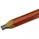
I swear depolarising MnO2 grime that dirtied my hands as a kid is still there, & the recall dissuaded from later plundering of spent AA cells. Although not 6B calibre, sturdy carpenters pencil leads make great carbon electrodes
 

Attachments

manie

Senior Member
NbT: You dont want Chlorine ANYWHERE near S/steel. It will corrode badly and quick...

Stan: Now thats a good idea ! Costs near nothing too ! I like the "drawing" of antennas on cardboard idea too... simple steps:
1 Draw antenna (Yagi/Quad/Whatever)
2 Measure = can improve
3 Fetch eraser
4 Shorten elements by rapid rubbing across draw lines
5 measure.....

Will it work ?
 
Top