BeanieBots
Moderator
OK, so it's another RGB fader.
However, this one has a few extra features but still only uses a 08M.
08M + 10uF decoupling
3 X 10k pots.
3 X 100R.
3 X 1k.
3 X 33k
1 X 10k
1 X switch
1 X RGB LED (or 1 of each R,G & B)
+ optional download circuit.
(don't forget to tie down serin if you don't use the download circuit)
Features:-
With switch off.
Each POT controls the brightness of each LED so any colour can be acheived.
With switch on:
Slow fade through all the colours.
The red pot controls the fade speed.
The green pot controls direction.
The blue pot has no effect.
So, how is that done with just an 08M?
It's actually very simple.
It uses the fact that all LEDs have a high Vforward.
That gives at least 1v that can be applied to the LED before it will start to conduct.
This means the ADC will only see 0v to 1v.
On a 5v rail with 8-bit conversion, that still gives a very useable range of about 50 values which limits the possible colours to 125000 possibilities.
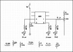
The circuit:-
Output 1 connects to 100R resistor then red LED to 0v.
33k to 5v to pot to 0v
Wiper of pot to 1k to Output 1.
Repeat for output 2 and green LED, output 4 and blue LED.
10k from input 3 to 0v. Switch from input 3 to 5v.
If anyone fancies doing a nice little ASCII sketch (hippy?),
please feel free.
How it works:-
It just time shares between each LED and a dummy pulse on output 4.
Between updates, the output is switched to input.
The analogue voltage from the pot (which is not affected by the non conducting LED) is then read.
The code is only an example of what you could do with such hardware. The rest is up to your imagination.
Enjoy.
However, this one has a few extra features but still only uses a 08M.
08M + 10uF decoupling
3 X 10k pots.
3 X 100R.
3 X 1k.
3 X 33k
1 X 10k
1 X switch
1 X RGB LED (or 1 of each R,G & B)
+ optional download circuit.
(don't forget to tie down serin if you don't use the download circuit)
Features:-
With switch off.
Each POT controls the brightness of each LED so any colour can be acheived.
With switch on:
Slow fade through all the colours.
The red pot controls the fade speed.
The green pot controls direction.
The blue pot has no effect.
So, how is that done with just an 08M?
It's actually very simple.
It uses the fact that all LEDs have a high Vforward.
That gives at least 1v that can be applied to the LED before it will start to conduct.
This means the ADC will only see 0v to 1v.
On a 5v rail with 8-bit conversion, that still gives a very useable range of about 50 values which limits the possible colours to 125000 possibilities.
The circuit:-
Output 1 connects to 100R resistor then red LED to 0v.
33k to 5v to pot to 0v
Wiper of pot to 1k to Output 1.
Repeat for output 2 and green LED, output 4 and blue LED.
10k from input 3 to 0v. Switch from input 3 to 5v.
If anyone fancies doing a nice little ASCII sketch (hippy?),
please feel free.
How it works:-
It just time shares between each LED and a dummy pulse on output 4.
Between updates, the output is switched to input.
The analogue voltage from the pot (which is not affected by the non conducting LED) is then read.
The code is only an example of what you could do with such hardware. The rest is up to your imagination.
Enjoy.
Code:
'RGB fun by BeanieBots.

setfreq m8				'clock it faster to reduce flicker

symbol RED_LED=1		'Red LED output
symbol GRN_LED=2		'Green LED output
symbol BLU_LED=4		'Blue LED output

symbol RED_POT=1		'Red brightness pot & sequence speed
symbol GRN_POT=2		'Green brightness pot & sequence select
symbol BLU_POT=3		'Blue brightness pot

Symbol POT_X = 3		'Analogue pot value multiplier
Symbol PL=900			'Pulse length
Symbol Rep=5			'Number of repeats to get reasonably slow fade.


b4=5						'set initial step size

main:
do until pin3=1
	input 2
	readadc 2,b5

	if b5 > 30 then 'do sequence 1, else sequence 2

	'Sequence 1, slow fade
	'blue to red
		for w0=1 to PL step b4
			w1=PL-w0
			for b6=1 to Rep
				pulsout RED_LED,w0
				pulsout BLU_LED,w1
			next b6
		next w0

		input 1			'get ready to read "RED" ADC
		readadc 1,b4

	'red to green
		for w0=1 to PL step b4
			w1=PL-w0
			for b6=1 to Rep
				pulsout RED_LED,w1
				pulsout GRN_LED,w0
			next b6
		next w0

		b4=b4/2+1		'Convert to number for step size to control speed

	'green to blue
		for w0=1 to PL step b4
			w1=PL-w0
			for b6=1 to Rep
				pulsout GRN_LED,w1
				pulsout BLU_LED,w0
			next b6
		next w0

	else

	'Sequence 2, slow fade other direction
	'red to blue
		for w0=1 to PL step b4
			w1=PL-w0
			for b6=1 to Rep
				pulsout RED_LED,w1
				pulsout BLU_LED,w0
			next b6
		next w0

		input 1			'get ready to read "RED" ADC
		readadc 1,b4


	'blue to green
		for w0=1 to PL step b4
			w1=PL-w0
			for b6=1 to Rep
				pulsout GRN_LED,w0
				pulsout BLU_LED,w1
			next b6
		next w0

		b4=b4/2+1		'Convert to number for step size to control speed

	'green to red
		for w0=1 to PL step b4
			w1=PL-w0
			for b6=1 to Rep
				pulsout RED_LED,w0
				pulsout GRN_LED,w1
			next b6
		next w0

		endif
loop


'Individual brightness control
do until pin3=0

	readadc 1,w0		'Get
	w0=w0*POT_X
	pulsout 1,w0
	input 1
	pulsout 0,w3		'Dummy to keep total time constant

	readadc 2,w1
	w1=w1*POT_X
	pulsout 2,w1
	input 2
	pulsout 0,w3		'Dummy to keep total time constant

	readadc 4,w2
	w2=w2*POT_X
	pulsout 4,w2
	input 4
	pulsout 0,w3		'Dummy to keep total time constant

	w3=660-w0-w1-w2	'
	w3=w3/4			'Dummy accounts for 1/3 but 1/4 makes things a little brighter

loop

goto main