Digital Clock :: DS1307 :: 2-wire LCD

George Sephton

Senior Member
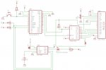
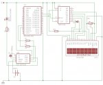
I have made a digital clock that will keep the time and display it on one line of a 16x2 LCD screen. The LCD screen is interfaced by 2-wire and a 74HC164.
Attached is the schematic and the code.
 

Attachments

lbenson

Senior Member
George,

Your R2 and R3 resistors are shown in-line on the I2C SCL and SDA lines. These lines should have 4K7 pullup resistors to 5 volts, and no inline resistors. I doubt that what you have will be reliable, and it will be less so if you add other I2C devices.

Look again at the diagrams in the I2C tutorial on pages 1 and 2.
 

BeanieBots

Moderator
The 28X won't work at all without a resonator or Xtal and leaving serin and/or reset floating will also produce erratic behaviour.
 

George Sephton

Senior Member
Wowowowo there's loads of stuff there Ive never heard about before, what is a pull up resistor? And I though the 28X1 didnt need to have a resonator, also how do I stop the serin pin being floating, my reset pin isnt though, just not in that schematic.
 

hippy

Technical Support
Staff member
@ George : Your diagram shows "28X" not "28X1" the former needs a resonator / crystal, the 28X1 does not. Serial In is stopped from floating by fitting the 10K/22K download interface, a pull-down resistor or wiring it directly to 0V.

You should also connect both VSS1 and VSS2 lines of the 28X1 to 0V. Plus add decoupling capacitors across the 28X1 and '164 power rails.
 

westaust55

Moderator
Wowowowo there's loads of stuff there Ive never heard about before, what is a pull up resistor? And I though the 28X1 didnt need to have a resonator, also how do I stop the serin pin being floating, my reset pin isnt though, just not in that schematic.
George,
In your earlier thread:
http://www.picaxeforum.co.uk/showthread.php?t=11220 at posts 4 and 12
ibenson and I previously discussed/clarified pull-up resistors.

I will say that your program code is well documented compared to many seen on the forum. :)
 

kevrus

New Member
I second Westaust on the code bieng well commented.

My own code writing is not very good by any standards (as I have zero experience apart from picaxe, or should that be %00000000 experience?) and comments are essential for my understanding. I started some code a while ago without comments, and I struggled when I returned to it a few months later...lesson learnt.
 

George Sephton

Senior Member
Just the clarify, I am currently updating this at the minute to include these pull up resistors, on my breadboard I do use pull up resistors its just not on the schematic. Ive also managed to include an alarm function too. As for the schematic showing 28X thats due to EAGLE having only the 28X, 18X and 08M not the whole lot, Ill see if I can change the name or something.
 

rbright

Member
Project Update Please George

George have you got the alarm function working & if so will you be publishing?
Have you tried circuit using a 18X which still has the I²C instructions.
Happy New Year
 

George Sephton

Senior Member
Sorry for the delay, I have re looked over it and created a script with an alarm function. It is not tested but I believe it should work although someone may need to correct my use of interrupt. The stop button and buzzer one might use for the alarm have not been included on the circuit attached but the rest is a copy of what I have had working well.
UPDATED: Circuit, BAS FILE.
Hope it works well.
 

Attachments

Top